In 2003 we remodeled our 1992 Starcraft Meteorite so camping wouldn’t be so Spartan. Part of this remodel included adding some electric appliances. We normally do not camp in campgrounds with hook-ups, so we needed to add a battery to run these new electric consumers.
Because we camp for up to two weeks at a time, some method of recharging the battery was required. We had two choices; the first was to purchase a gasoline powered generator or a solar system. Generators require maintenance and fuel, not to mention they are noisy. So we decided to go solar. Not knowing anything about solar systems, I spent several months researching. The first step was to determine how many amp hours we would typically consume per day, then to figure how big a battery bank we would need and lastly how many watts (or amps) we would need in a solar system. Also we needed to decide what our solar (or battery charging) strategy would be.
Solar Strategies
I came up with three possible strategies:
- Provide enough battery charging so by the end of two weeks our battery bank would not be below 50% of the rated amp hours (I call this just in time charging).
- Provide enough battery charging so that by the end of each day our battery would be fully charged (this assumes perfect weather).
- Provide enough battery capacity to keep battery amp hours above 50% should we have a week of bad weather, and have the ability to fully charge the battery bank in one day of good weather (optimum) system.
I went with option #3. The first thing I needed to do was calculate the anticipated daily amp hour usage. Once I knew this number I could calculate how many amp hours I needed in my battery and then how many amps required to recharge a 50% battery bank in one day.
The table below provides typical amperage for electrical consumers. Multiply the amps by the number of anticipated daily use, then add up everything.

We had no experience with electrical devices for camping so I estimated high. I also factored in a 12 volt box fan to be used 7 hours a day in really hot weather. So my worst case scenario came to 15 amp hours per day.
Now I had to figure out how many Available Amp Hours different batteries have. At first this was difficult because many manufacturers do not rate capacity in Amp Hours. Also we needed a “deep cycle” battery, not an automotive type battery. Deep cycle batteries are designed to be discharged repeatedly, as long as the battery charge does not go below 50% of the rated capacity.
I found the Interstate brand of RV/Marine batteries to be most available and reasonably priced. But the specifications for Interstate batteries are Reserve Capacity (minutes) at 25 amps. A Google search provided the formula to convert this number to amp hours:
Reserve Capacity ÷ 2.4 = Amp Hours
An Interstate Group 27 battery has a reserve capacity of 180 minutes, which can be converted to 75 amp hours. Since we do not want to use more than 50% of the batteries capacity, it would take two Group 27 batteries to give us a useful capacity of 75 amp hours. Assuming a maximum daily usage of 15 amp hours per day, two of these batteries would last 5 days without going below 50% of the battery bank capacity. Click here to see pictures of battery installation.
Now I had to determine how much solar would be required to recharge the battery bank in a day of full sunlight. I found a Kyocera KC-120 panel that was rated at 120 watts, or 7.1 amps. This panel could produce (in sunny weather) about 55 amp hours per day in summer, or 40 amp hours in winter. Not enough to provide my goal of 75 amp hours in a single day, but I had little experience. Plus it would be easy to add a second panel if needed.
Now I had to determine what kind of panel (construction) to buy. There are three types:
- Monocrystaline Silicon
- Polycrystaline Silicon
- Thin Film (usually amorphous silicon)
Without getting into a long technical discussion I went for the Kyocera Monocrystalline panel.
Advantages
- Highest efficiency
- Space efficiency
- Longest life
Disadvantages
- Most expensive
- Partial shade significantly reduces output
The next order of business was wiring and a charge controller. The bottom line on wiring is that thicker wire has less resistance, which means more amps to the battery. Always go for the thickest wire available. I don’t remember the gauge I used, but it did have an ultra-violet protective sheath.
Charge Controller
Since my panel can product over 17 volts, the voltage needs to be dropped down to meet the requirements of a 12 volt system. There are several types of controllers and the best ones allow the owner to adjust the charge point. The problem with most charge controllers is that they are set at a charge rate of 13.8 to 14.2 volts. This is in contrast to the specifications of what most battery manufacturer’s state, which is 14.8 volts! I ended up with a 15 amp charger controller made by Specialty Concepts, which is a Pulse Width Modulated (PWM) unit.
If one camps in varied climates, an excellent option for your charge controller is to get one with a temperature sensor. Battery state of charge is temperature dependent.
The darling of the solar industry today is the MPPT (Maximum Power Tracking Point) charge controller, which happens to be the most expensive type of controller and is really for large solar systems such as a house system. There is little advantage to using these systems on an RV.

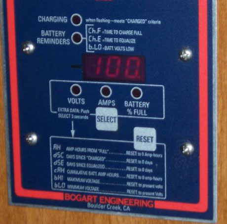
Above: Although the controller is set at 14.8 volts, the charge is reduced as the battery reaches full so it does not overcharge and boil the electrolyte.

Above: The controller panel can be switched to read the charging amps.
The State of Your Battery
Most people wouldn’t go on a long trip without a gas gauge in their vehicle. The same goes with your solar system, you need to know how many usable amp hours are in your battery bank.
Many RV owners insist on using a volt meter to determine the state of charge of the battery bank. The problem with this is that a battery should be left disconnected for 24 hours to accurately determine its state of charge. I think the decision to use a cheap volt meter to try and determine the battery state of charge is driven by prices. Voltmeters are cheap and not accurate in determining the state of charge of a battery bank that is connected to the RV’s electrical system.

The right tool for this job is a Battery Monitor. It measures the amps into and out of the battery. I will tell you exactly how many useable amps are in the battery bank. Good one’s like the Trimetric 2020 (bogartengineering.com) will provide all kinds of useful information, such as percent of charges, amp hours remaining, voltage, etc. After using mine for almost 10 years, I would not consider camping without it.
Installation
There are several ways to do this:
- Make them portable and able to move around (a hassle, chance of tripping over cables, or breaking a panel.
- Roof Mounted (convenient)
- Roof Mounted with the ability to tilt during the day for optimum solar collection (a pain in the butt)
I chose option number two; fixed installation on the roof. Just make sure that other roof accessories cannot cast a shadow on your panels. Also you cannot park in shade, but why do that? The RV has its own shade. For use we are not in our camper during the day anyway.
Special Considerations for tent trailers. Since the roof goes up and down, installation is not as straight forward as a travel trailer or motor home installation. Here is how I did it on both of our tent trailers.
1992 Starcraft Meteorite

Above: Unpacking the Kyocera KC-120
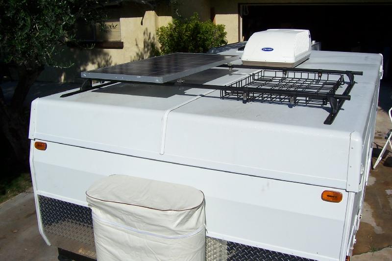
 Above: Panel mounted on roof. Note that the vent is next to the panel which can cast a shadow. We would normally keep this closed at night… are walls are tent material after all. We would only open the vent when taking a shower, as the vent is directly over our shower.

Above: Cable is routed through the roof.
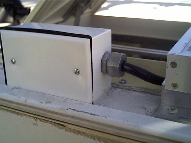
Above: The box for the cable routing is water proof.

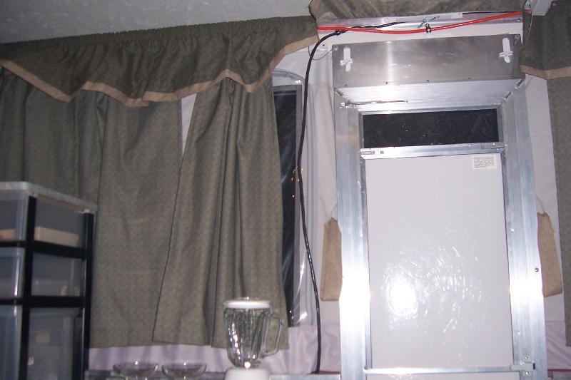
Above: Running the cable inside the camper.

Above: The cable is hidden under the valance curtain.

Above: The cable now exits the camper. It is long enough that we can push the cable inside the camper along with the tenting material when lowering the roof during take down. Then cable is routed back into the camper body back into the camper where it is connected to the charge controller.

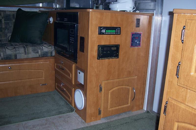
Above: Cable is routed inside a cabinet where the charge controller is mounted.
2005 Fleetwood Niagara
When we first purchased this camper we simply transferred the solar system and batteries, knowing we would probably need to upgrade the system with a larger battery bank and an additional solar panel. The first thing we did was to change out the 5 gallon propane tanks for two 10 gallon tanks.

Above: dual Interstate Group 27 batteries, Kyocera KC-120 solar panel, and new propane tanks.
The installation of the panel and wiring was similar to our Starcraft. The only thing I did differently was to all some Yakima Track Racks and carrier bars. These are the exact same track racks that Fleetwood installs on their roofs. I opted to do the work myself because it was cheaper, and as a ASE Master Technician the quality of my work is much better than the factory assembly guys or the dealer’s service department. This way I could mount the panel on the rack. I used Yakima Locks to secure the panel to the racks.

Above: Instead of drilling a hole in the roof to route the wiring, I was able to run them through the roof top air conditioner unit (above).

Above: close up of wiring through the A/C unit.
Above: Installation complete. Another reason I used the rack to mount the panel is to get it high enough so the A/C unit doesn’t cast a shadow on the panel.
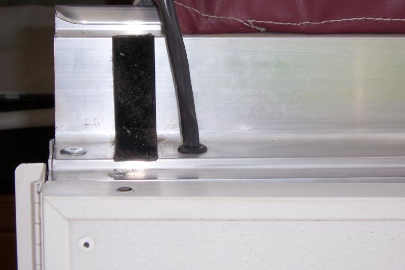
 Above: The power cord for the A/C unit (left) and the solar system (right) are routed through the roof support channel.
Above: The black cable is for the solar system and the orange one the air conditioner.

Above: The cables are hidden from view by the curtains. Note the Margarita blender on the left 🙂
Above: Just as I did with the Starcraft, the cable exits the interior of the camper and then is routed through the body back inside and into a cabinet. This allows the cable to be pushed back into the camper with the tenting material when lowering the roof.

Above: Charge controller (lower left) and Trimetric battery monitor (lower right). The on/off switch at the upper right is for the interior lights.
 Above: The solar wiring runs through the charge controller, then the battery monitor, then through a shunt for the battery monitor, and finally to the battery. Note the heavy duty cable.

Above: We also added a 750 watt (1500 peak watts) to the system. Again note the heavy cables. The white tape indicates ground. RV’s use white wiring to indicate ground and black for positive on the 12 volt circuits, which is different than cars and trucks that use black for ground and red for positive.
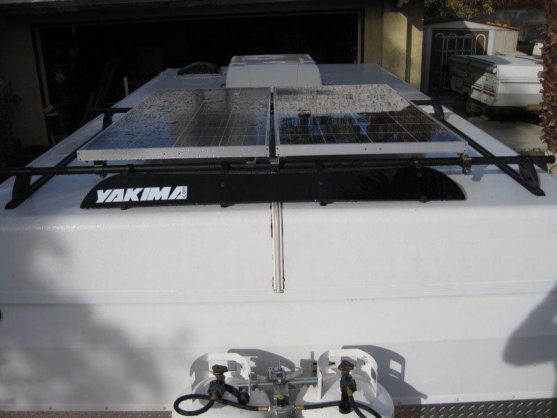
Above: Because of the additional electrical needs of this trailer (especially the forced air furnace), I added a second Kyocera solar panel rated at 130 watts, giving us 250 total watts, and the potential to put 80 – 110 amp hours back into the battery bank daily.
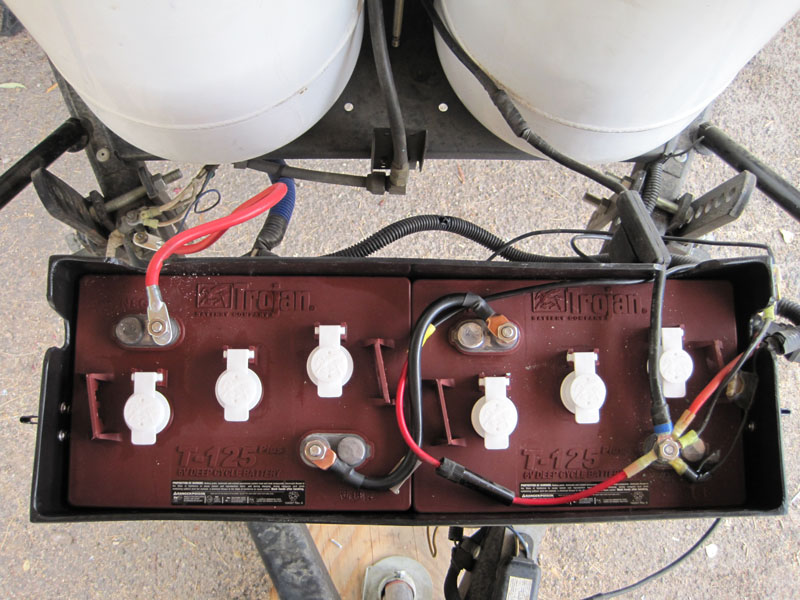 Above: I also replaced the Interstate Group 27 batteries with two Trojan T-125 true deep cycle batteries with a total amp hour rating of 240 amp hours, or 120 usable amp hours per day. More details on the Trojan batteries can be found here.