Sizing an RV Solar System: Part 4
For 10 years our travel trailer’s 280 Watt solar system served us well. We never had a dead battery, even when camping for 30 days in the same spot. Since retirement our camping habits have changed and it was time for some upgrades. This article will look into the options of upgrading (adding on) an existing solar system, along with some of the sand traps and water hazards of the upgrade path.
If you are new to solar systems and haven’t read the earlier posts in this series, here are the links:
Sizing an RV Solar System: Part One
Sizing an RV Solar System: Part Two
Sizing an RV Solar System: Part Three
In addition, these articles contain more detailed information on battery monitors and the two kinds of solar charge controllers:
TriMetric Battery Monitor — 20 Year Review
Solar Charge Controllers — PWM vs. MPPT
Remote Power System for Telescope
The Old System
Not only did we get by with our 280W solar system, but until the beginning of 2022 we were fine with 225AH (Amp-Hour) flooded lead-acid batteries. Last year I replaced the heavy and maintenance-required battery bank with a much lighter and higher capacity 300AH LiFePo4 (lithium iron phosphate) battery, which I documented here.
Changing Needs
In that article I shared that we typically used between 22AH and 45AH each day. We also needed enough reserve capacity to power our camper for five days should the weather turn bad and the sun stop shinning. If the weather was poor we would have to monitor our electrical use more closely. We could not use 45AH per day as it would completely drain our old 225AH and probably ruin it. In addition, running down a flooded lead-acid battery to below 50% of capacity too frequently will shorten its life-span.
When we are camping we aren’t hanging out in the camper all day. We are out doing things, mostly hiking. So we aren’t using electricity when we are gone. In poor weather we spend more time in the camper, meaning we are using more electricity.
LiFePo4 Battery
This website may be compensated for linking to other sites for sales of products. As an Amazon Associate I earn a small fee from qualifying purchases at no additional cost to the purchaser.
This battery alleviates these issues with flooded-lead acid batteries. Draining it down to zero won’t hurt it. Although doing that too often will shorten its life. LiFePo4 batteries can also be recharged many more times than conventional batteries; 5 to 10 times more dependent upon how much energy is used daily. Our new 300AH has 33% more capacity than what we had used for the past 10 years.
We Use More Energy Now
We are now retired and all of our trips are longer. No more short weekend or 4-day trips. Our minimum is two weeks and we often are out for a month or longer. It used to be if the weather was going to be really poor for a week or more, we’d just go home. Nowadays we might be 1,000 miles from home and don’t need or want to cut a trip short.
Since we normally don’t have to be as concerned with how much energy we use each day with our larger battery, I now monitor usage less. I might look at the battery percent full a couple times per day.
Instead of 22AH to 45AH per day, we are now averaging 30AH to 60AH per day. Part of this is powering my laptop because on long trips I have to pay bills in our absence from home. In addition to this, for the past couple of years, I have been bringing my telescope and cameras on many trips, using an additional 22+ amp-hours each night. Even if I power the telescope with a separate battery, I am controlling things with my laptop.
Thus our 280W solar system had become undersized for our battery and our use.
Designing the Solar Upgrade
In Part Two I discussed the optimum charge rate for a battery, where a rate of 20% of the battery’s capacity is optimum. In Part Three, I shared a real world tool that estimates how much energy a solar system will actually harvest. This is the tool I used to size our new system.
Battery Charge Rate
20% of our 300AH capacity battery is a charge current of 60 amps. This would be ideal. A little less won’t hurt it, it will just take longer to charge. The battery manufacturer states anywhere from 20% to 50% is recommended, with 20% being ideal. For our system the preliminary goal was a charge current between 60 to 150 amps. Though 150 amps is huge.
Even if a solar system can provide 60 amps of charge current, with our horizontal roof mounted panels, the system’s charge rate will vary with the position of the sun as it moves across the sky and its altitude higher or lower depending on the time of year.
The solar system I installed in 2013 has a maximum power current of 15.82 amps. Adding more panels to to get a charge current of 60 amps, would require and additional 44.18 amps. More important, as I explained in Part Three, is the number of watt-hours a system generates.
Limits Of Our Old System
First and foremost was our Pulse Width Modulation (PWM) solar controller that has a maximum of 45 amps. I could only add about 30 amps to that controller, even less if I stay within industry recommendations to size the solar panels to 25% less than the solar controller’s rating.
In addition to this limit, our panels are now over 10 years old. Back then, common solar panels recommended for 12 volt systems on RVs were rated at 17-18 volts at maximum power. Today, most are around 20 volts or higher. Mixing panels with different voltage or current specifications isn’t optimal.
Would I Have To Remove Our Old System & Start Over?
This was the big question. I had no qualms about removing a system that was quite expensive 10 years ago. But why would I want to remove a system that should perform within 90% of its specified output for 25 years or so? Not only would it be expensive; I hate discarding things that work well just to get the “newest and greatest.”
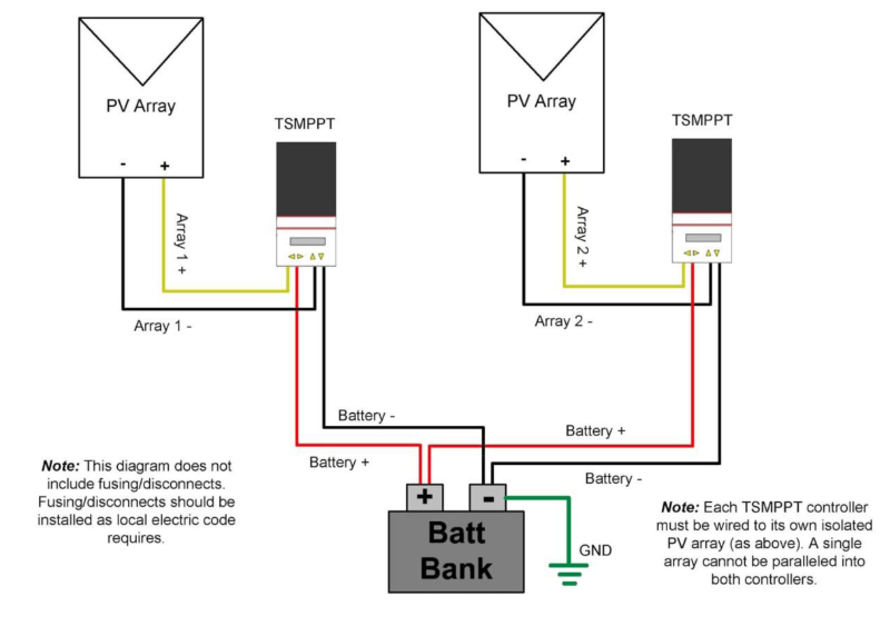
I wondered if there was a way to keep our old panels and solar controller. I found the answer in this article, Parallel Charging Using Multiple Controllers With Separate PV Arrays, published by Morningside Corporation, one of the largest solar charge controller manufacturers in the US.
Not only is connecting two separate solar arrays to a single battery acceptable, there is no degradation in charging the battery, even if both a PWM and MPPT controller are used. One caveat though — both controllers must have the same charging profile (Morningstar is assuming their charge controllers are being used)
-
- Use the same DIP Switch settings for matching the charging control.
- If a custom setup is used with Morningstar’s software all settings must be the same.
- There must be a connection from the battery bank to each controller’s Voltage Sense terminals.
- If a Remote Temperature Sensor is used (not used with LiFePo4 batteries) separate sensors must be connected to each controller.
During charging, the two parallel controllers will start limiting the voltage at approximately the same time, since they will be sensing the same voltage and have the same charging profile.
As I wrote in Part one, any system of around 600 watts or higher will get the maximum power if a MPPT charge controller is used. As it turns out, adding a 600W array to our current system will get us close to 60 amps of charge current.
Calculating A New Array Using The Charge Current
If we add a 600 watt array to our current system it will add an additional 41 amps of power, if I use a MPPT charge controller. This formula provides the calculation:
Watts = Volts X Amps
Amps = Watts ÷ solar charger set point Volts
Amps = 600W ÷ 14.6V
Amps = 41.09
Adding 41.09 additional amps to our existing 15.82 amps would provide a maximum current of almost 57 amps (56.91). Meaning that if we use 20% of our capacity, or 60 amps, we can fully charge the battery in just over 1 hour under ideal conditions and time of year.
The three panels together have a maximum current output of 31.26 amps. However, from my MPPT vs PWM article, a MPPT, unlike PWM, controller modulates both voltage and amps and will output more than the charge current from the panels, thus the 41 amp calculation above.
Calculating A New Array Using Watts And Watt-Hours
The Old System
To figure out how many watts our old system can generate with a PWM charge controller the formula for determining how many watts an array can harvest is:
Watts = Charge Current X Nominal Battery Voltage
Watts = 15.82 Amps X 12.8 Volts (LiFePo4 Battery)
Watts = 15.82 X 12.8
Watts = 202
This is only 72% of the rated 280 watts of the existing solar system, a limitation for PWM controllers.
Adding Additional Panels and a 2nd MPPT Controller
Because a MPPT controller modulates both voltage and current, it will provide all of the specified watts. A 600W solar array can provide 600 watts of energy using a MPPT controller. The old array along with a new 600W array will give us 802 watts:
Watts = Old Array + New Array
Watts = 202 + 600
Watts = 802
PVWatts Calculator Tool
In Part 3, we used an example of a 800W system to determine how much solar we can harvest. Using this data, our upgraded solar system will perform as follows:

We camp year round. Summers in the mountains. In the cooler months you will find us in the deserts of Southern California, Nevada and Arizona which are just gorgeous in January, February, November and December — months that our solar system can only harvest about half the energy that we get in May thru August. We needed to size the solar system to provide enough energy in those winter and fall trips.
If the weather is really crappy, our battery monitor allows us to watch of electric consumption and conserve as needed. Assuming no sun at all for 5 days, and an average use of 40AH per day, we will deplete our battery capacity by 67% and consume 200AH out of 300AH. With a LiFePo4 battery, this is acceptable. We also need to keep in mind that the solar panels will still harvest some energy on cloudy days. The table below shows 200AH of use for every month of the year, based on our latitude and longitude, and how long it will take to put 200AH back into the battery.
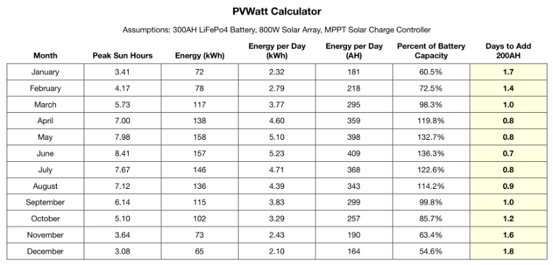
The table above uses a 800W solar array, a MPPT solar charge controller, and a 300AH LiFePo4 battery. Our new system will have 880 Watts but 280 of those watts will be used with a PWM controller giving us only 202 watts of energy in addition to a 600W array with a MPPT controller for a total of 802 Watts.
We have never gotten to the point where we needed to add 200AH back into our battery bank. The most has been about 100AH during a cold and rainy December in the Nevada desert. It is best to over-spec a system in case energy needs change, especially in this day and age of so many electronic devices and appliances.
The new system will easily fit our needs. I should also point out that the 22+ amp-hours consumed by my telescope system will be charged by the 100W Renogy Suitcase Solar Panel Kit I shared in these two posts:
Sizing an RV Solar System: Part 1
Remote Power System for a Telescope
I ordered three Renogy 200W solar panels, a Morningstar TriStar 45A MPPT controller, plus a bunch of hardware and cables.
The Old 280W System

I left this solar array and controller in place. Below is the wiring diagram I used to install it 10 years ago and this is a link to the article describing the installation.

The new 600W solar array string leaves everything from the original 280W system in place, other than we have replaced the two 225AH, 6 Volt batteries wired in series with a single 300AH LiFePo4 battery.
The new 600W system is added to the existing configuration. This includes:
- Three Renogy 200W panels
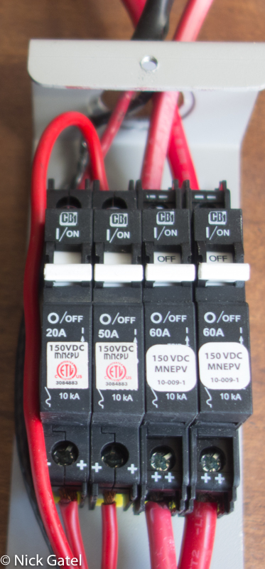
- Two MidNite Solar 60A circuit breakers, which were added to the existing MidNite Solar Baby Circuit Breaker Box
- A Morningstar TriStar 45A MPPT Solar Controller
In summary, the new 600W solar array is connected to the battery along with the original 280W solar array. Nothing in the original system was changed.
Installation
Shading
One challenge with RVs is shading. Not only are there all kinds of things on the roof that can shade a panel, campsites can have trees that will cast shade on panels. Of course if you camp in dispersed sites like we often do, you can usually park your RV in a non-shaded spot.
In Part Two, I discussed the pros and cons of wiring panels in series or parallel. Series connections require fewer components, but do much worse in partial shade.
Impact of Shading on Panels Wired in Series
When solar panels are wired in series, the current (amps) remain the same, but the voltages are added up. If we have four 200W, 19.2 Volt, 10.42A solar panels wired in series, our array becomes a 800W array at 76.8 Volts and 55 amps using a MPPT controller.
The volts and watts are added up:
Watts = 200 X 4 = 800W
Volts = 19.2 X 4 = 76.8V
MPPT Controller Charging Amps = Watts ÷ Charge Controller Set Point
Charging Amps = 800W ÷ 14.6V = 55A
When one panel in a string of series panels is shaded, the voltage of the string remains the same, but current of every panel drops to that of the shaded (lowest) panel. The diagram below shows this. The total charge current from the MPPT controller goes from 55A to 26A.
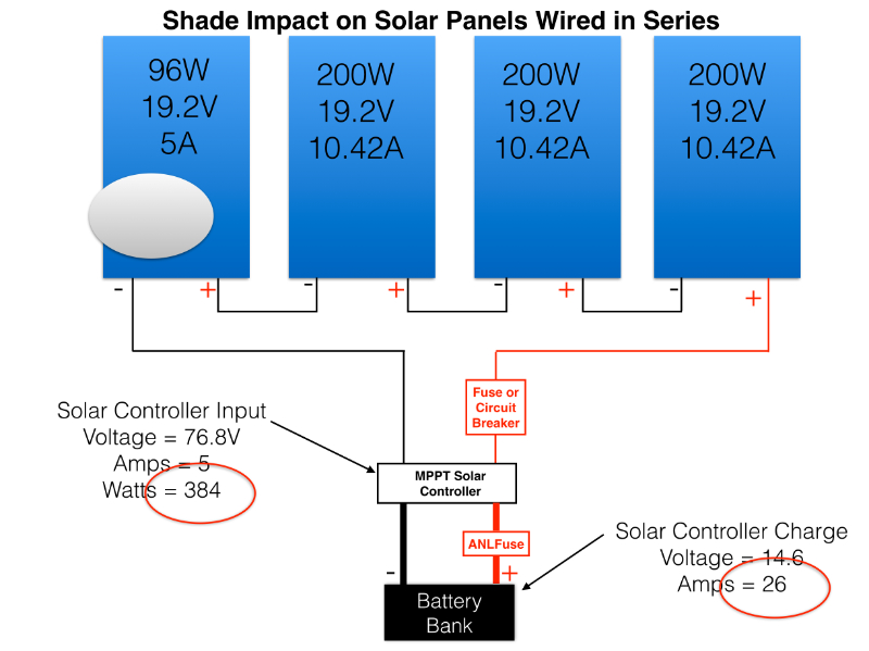
Impact of Shading on Panels Wired in Parallel
With a string of panels wired in parallel, the voltage stays the same and we add up the current of each panel. In the diagram below, the current in the shaded panel has dropped from 10.42A to 5A. In a parallel connection, we add up the current for each panel:
Total Charge Amps = 5 + 10.42 + 10.42 + 10.42 = 36A
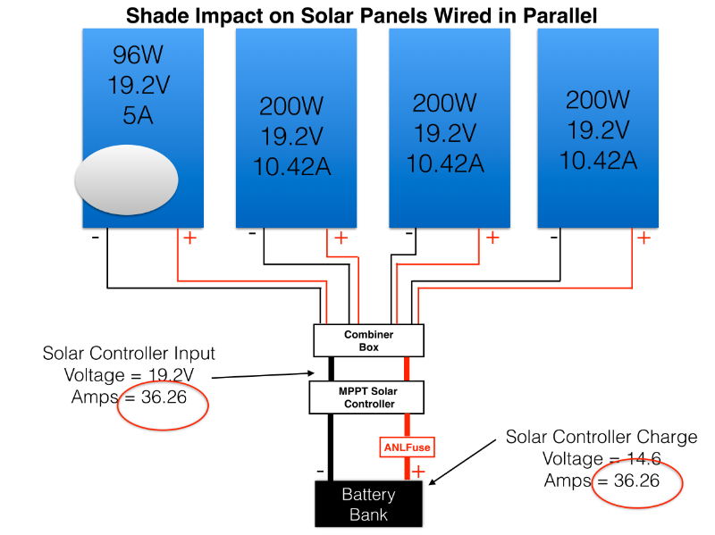
With the same exact shading in both examples, a parallel string will output 38% more energy than the string wired in series. It seems that a lot of RV owners with larger systems have their panels wired in series, because it is much easier and cheaper.
Locating Our New Panels
With potential shading in mind, I first laid out the panels and then did some calculations.
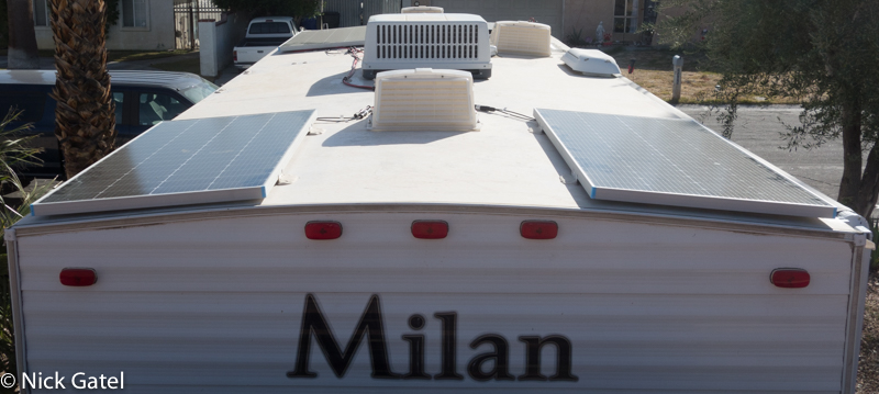
Below the three new panels are laid out as close as possible to the original two original possible to save on solar cables and other hardware, plus to minimize any voltage drops.
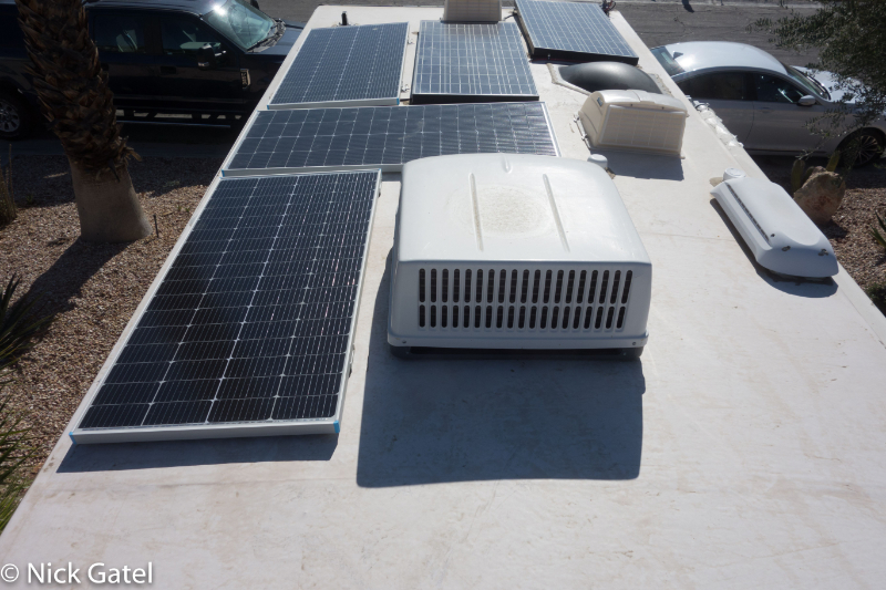
The front of the camper (top of picture) is facing exactly due south. The picture was taken on Dec 1, 2023 at 2PM. The sun is 25° above the horizon with the zenith around noon at 34° above the horizon.
There is a large shadow from the air conditioner in the center of the picture. If the camper were rotated 90° or 180° counter-clockwise there would a large shadow on one of the panels. Fortunately we can predict and calculate how long the shadow will b for different times and days of the year.
Calculating Shadows
From the website we can find the altitude of the sun for any day or any time.
Below is the position chart for Dec 1, 2023 when I took the above picture. For that day, the sun is at its highest between the hours of 10AM – 1PM, which is when we will get the most sun and the shortest shadows.
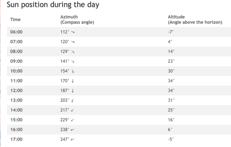
With a little math and spreadsheet we can construct a table predicting the length of any shadow.
The formula requires calculating the Tangent of the sun’s altitude (angle above the horizon). For those who forgot how to do this from their high school trigonometry class, a modern calculator or a website calculator can do this quickly. Older folks like me no longer need a slide rule.
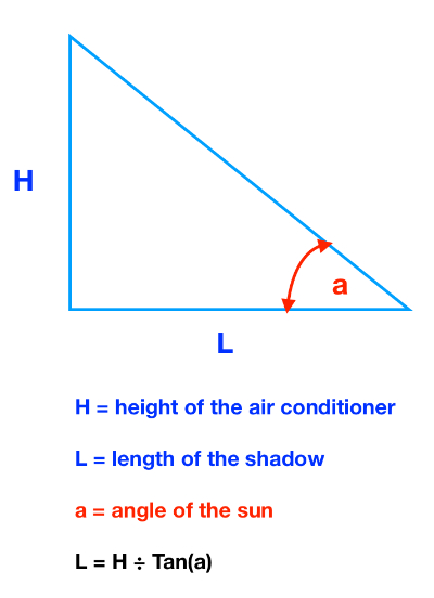
In the example below I built a table for my location with the length of the shadow when the sun is at its highest point (zenith) on the 21st day of each month of the year.
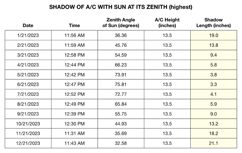
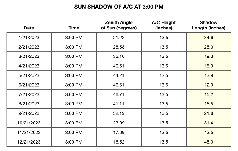
And a table with the length of the Sun’s shadow at 3 PM for the 21st day of each month of the year.
Here’s (below) a picture of the final location of all the solar panels at 3 PM on Dec 8, 2023.

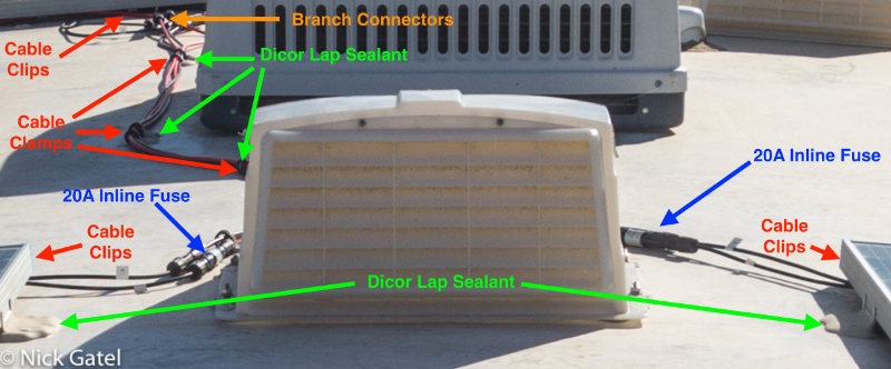
To minimize the effects of shading, the three new panels (bottom two and upper left) were wired in parallel. This required heavier gauge extension cables, a fuse for each panel and some cable clamps and clips to secure the long runs of cable to the roof (to keep cables from flopping around).
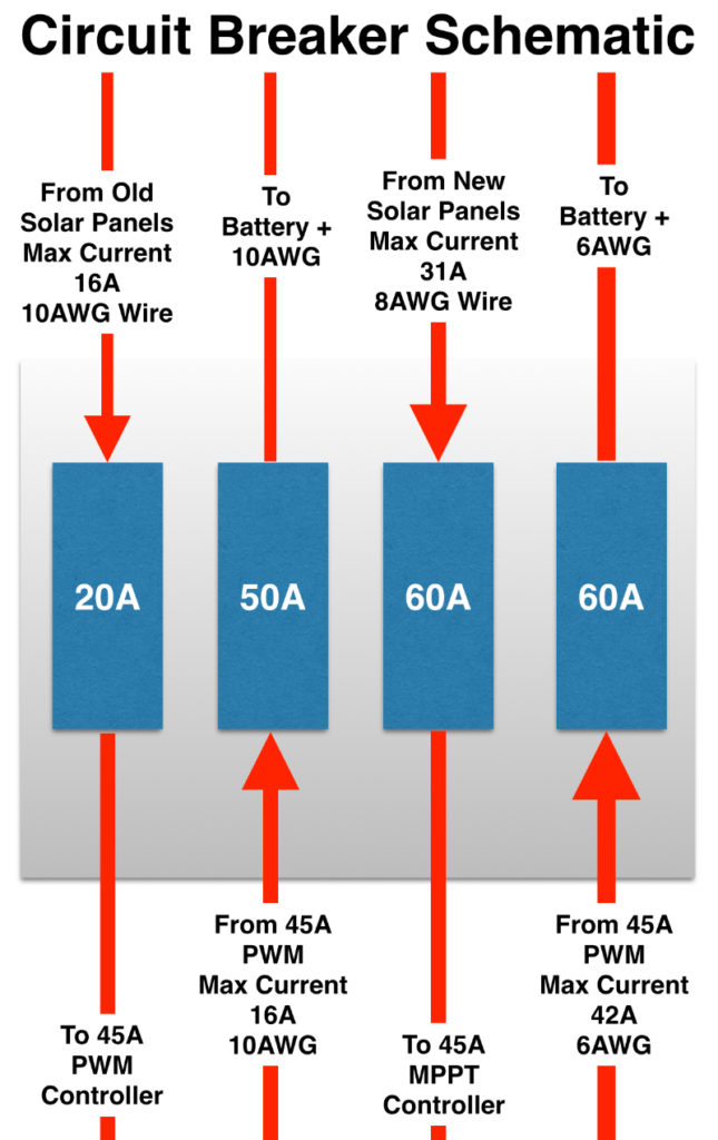
Below is a schematic with the new components and wire gauge identifications.
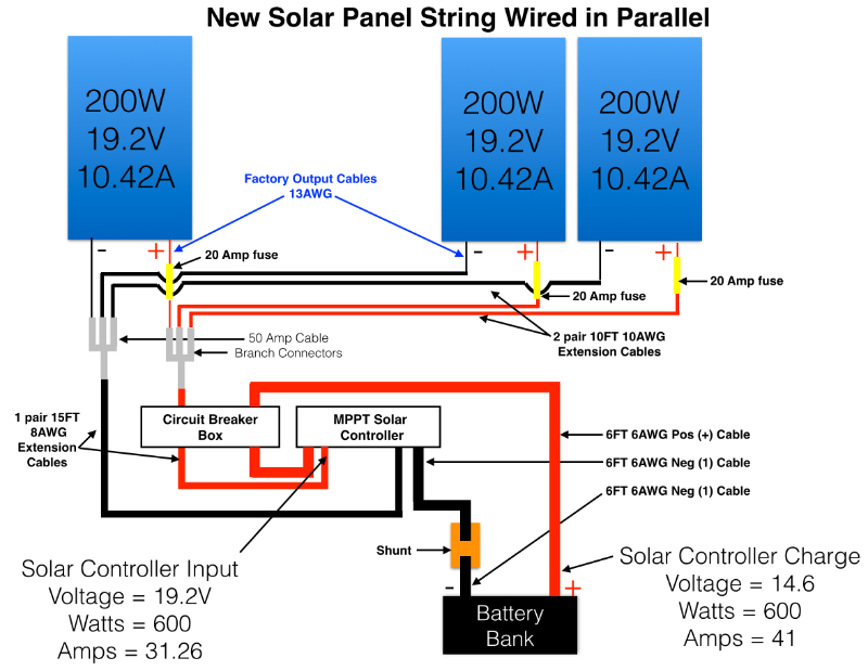
New Panel Array Installation
Z Brackets
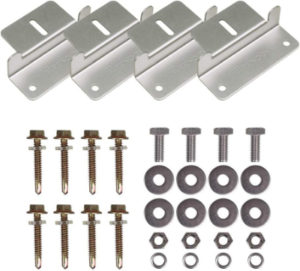
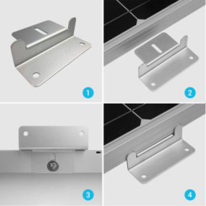
To mount the panels on the roof, I purchased a set of Renogy Z Brackets for each panel. On the original panels, which only had one mounting hole, I used well nuts.
Each of the Renogy Z Brackets have two roof mounting holes. Using the included screws and “leak proof” washers I mounted all three panels in less than an hour.
Cables & Hardware
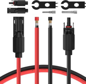
All cables on the roof and inline fuses come with waterproof connectors that are just plugged together. No stripping wires, no wire terminal connections with screws or crimp connectors, nor any soldering. Quite an improvement over what I had to do in the past.
The integrated cables for each panel are about 30 inches long and are 13 gauge (13 AWG).
All the cables I bought come with an outer UV protective coating, which is a must have!
Fuses
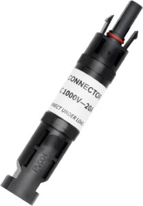
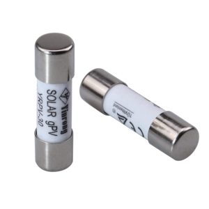
I installed a 20A inline fuse in the positive lead of each panel (three total).
Extension Cables for the two rear panels
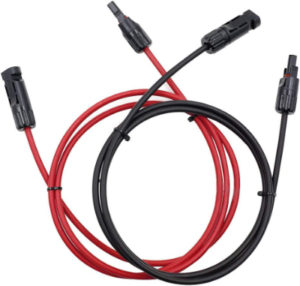
Each of the two rear panels required a pair of 10 foot extension cables. I used 10AWG to minimize any voltage drop.
Cable Branch Connectors
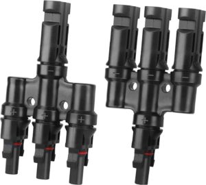
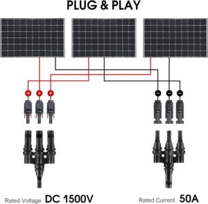
With the two pairs of 10AWG extension cables for the rear panels, I was now able to connect all three panels together in parallel with branch connectors. Three panels in parallel will have a maximum output current of 31.26 amps. Finding branch connectors with a rating greater than 30A is somewhat rare. I was able source 50A branch connectors on Amazon.
Main Cable to Circuit Breaker
The branch connectors connect three panels into a single output cable that goes to the circuit breaker box. This cable would need to be rated to carry just over 30 amps. I bought a pair of 8AWG cable extensions and used 15 feet.
One end does not come with connectors installed, which was perfect as they would be connected to the circuit breaker box and controller.
Routing Cables From Roof Into The Trailer
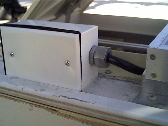
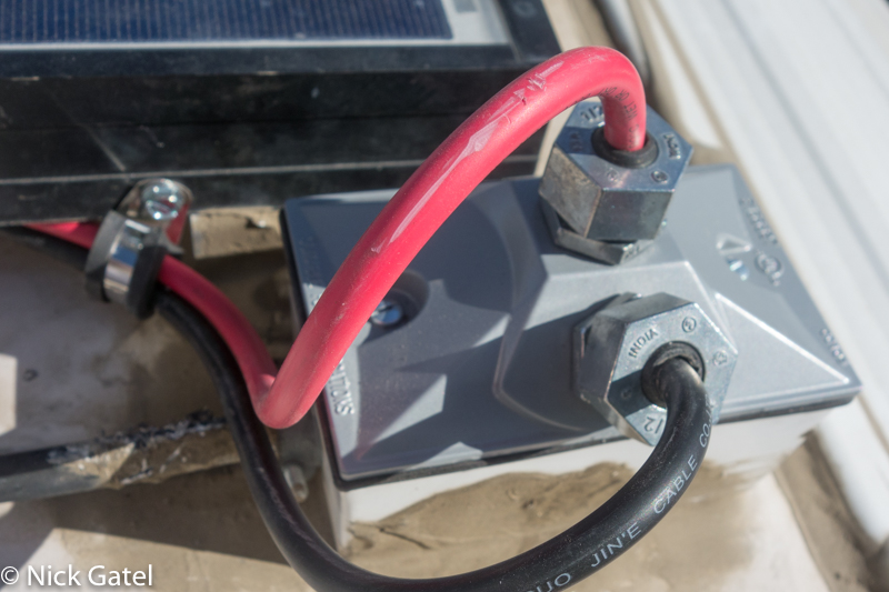
Today one can buy a specialized waterproof roof gland to run wires through the roof. These didn’t exist (that I know of) when I installed three different solar systems over the past 20 years. What I used was a waterproof electrical box. I decided to route the new wires through the same box that has never leaked.
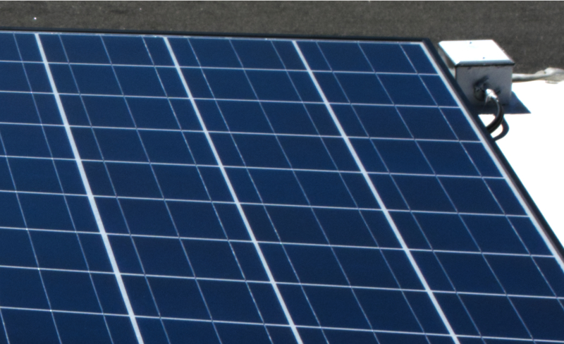
I don’t have close up pictures of the current box, but below are two pictures of the same kind of box used on our 1992 Starcraft Meteorite tent trailer (below).
The existing solar system wiring had been routed through the side of the box as above. The new 8AWG wires for the second solar string I was installing were much thicker and it would have been too much of a bend to run them through the side of the box.
I bought a new box top with wire glands and a rubber gasket. I had to drill a new large hole through the bottom of the box and into the roof. I would later further seal this box with Dicor Self-Leveling Lap Sealant.
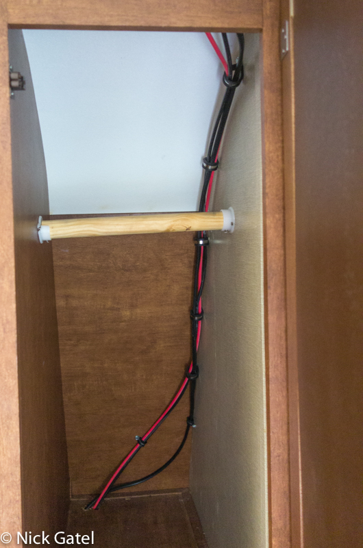
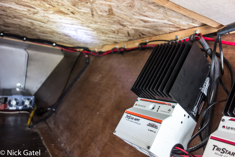
The rooftop waterproof box is mounted just above one of the closets in the trailer. In the picture below, the new 8AWG cables are routed alongside the 10AWG wires from the original 280W panels. The wires exit the bottom of the closet into pass-thru storage compartment where the solar controllers are mounted. This method is the shortest path, which I wanted to use to minimize any potential voltage drop.
Securing Cables on the Roof
To keep the cables on the roof secure I used cable clamps and some cable clips.
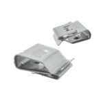
The cable clips secure wires to the solar panels. I used two different sizes for the different gauges of wire. These clips can also be used to route wires along the frame of the trailer for other applications.
Also used several cable clamps to route the longer run of wires. I used sheet metal screws to attach them directly to the roof and later sealed them with lap sealant.
Connecting Wiring to the Circuit Breakers, Solar Controller and Battery
The new 600W solar array string has individual 20A inline fuses at each panel, which is a best practice. With these fuses, we don’t need a circuit breaker for the new string.
But a circuit breaker makes it easy to disconnect the array from the system should some sort of maintenance or repair be needed. The circuit breaker panel is configured as follows:
- 20A for Solar Array #1 — max current in ~ 16A, 10AWG wire
- 50A for PWM Controller Out to Battery — max current out 16A, 10AWG wire
- 60A for Solar Array #2 — max current in 31A, 8AWG wire
- 60A for MPPT Controller Out to Battery — max current out 42A, 6AWG wire

Inside the storage compartment the wires and cables for the controllers, circuit breaker box, meter displays, battery, inverter, system fuses and other items are routed with 1/2” and 1” cable clamps along with spit wire looms. We store items inside the compartment and need to back sure the wires and cables are damaged or moved when traveling if any of our storage items shift.
System Monitoring Displays
(left to right) TriStar Remote Display for MPPT controller, TriMetric 2030-RV Battery Monitor, TriStar Remote Display for PWM controller, Samlex Inverter Remote Display.
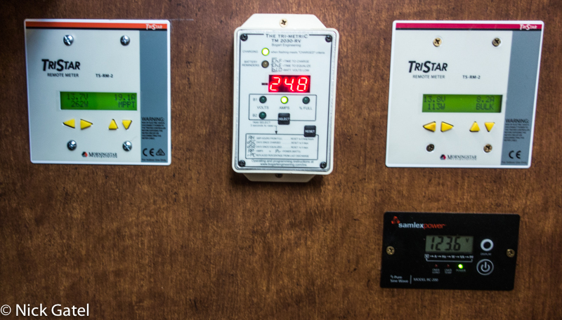
The MPPT display shows the charge rate at 19.1A and the PWM is charging at 8.2A for a total of 27.3A. The battery monitor shows 24.8 amps going into the battery, which is 2.5A less than what the solar displays are reporting. This makes sense because the inverter display (lower right) shows the inverter is on and supplying 123.6 volts AC current to the trailer. The inverter draws 2.5A when nothing is being powered by it. The system is working perfect.
Final Completion Step
Once everything was installed and proper operation verified, it was time to seal any potential leaks on the roof from installed components.
I used Dicor Self-leveling Lap Sealant. This is awesome stuff and as it levels after application, it seeps into the nooks and crannies that could be a potential leaking point. It is applied using a caulking gun. Apply it liberally!
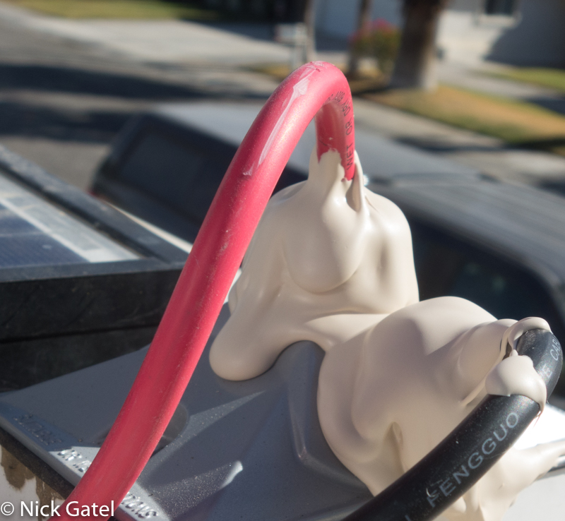
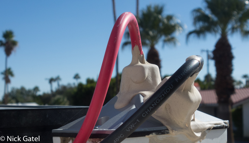
Even after several years the lap sealant remains somewhat flexible and isn’t too difficult to remove if needed. A putty knife will remove most of it.
Material List
More detailed information for the original 280W components, the 300AH LiFePo4 battery installation located in the storage area, and the new 600W components can be found via these links:
JITA 12.8V 300AH LiFePo4 Battery
(3) 20A Fuse Holders with Fuse
(2 pair) 10AWG 10FT Solar Extension Cables
(1 pair) 50A 3-1 Solar Branch Connectors
(20FT) 8AWG Solar Extension Cable Pair
Sigma 1/2-Inch 3 Hole 1-Gang Box
Sigma 1/2-Inch 3 Hole Gang Box Cover
(1 pkg) 23mm Double Wire Solar Wire Panel Clips
(1 pkg) 21.6mm Solar Wire Panel Clips
MidNite Solar Baby Box (circuit panel box)
MidNite Solar 20A DC Circuit Breaker
MidNite Solar 50A DC Circuit Breaker
(2) MidNite Solar 60A DC Circuit Breaker
(3) Dicor Self-Leveling Lap Sealant
Morningstar TriStar 45A MPPT Solar Charge Controller
Morningstar TriStar 45A PWM Solar Charge Controller
(2) Morningstar TriStar TS-RM-2 Display
Bogart Engineering TriMetric 2030-RV Battery Monitor
2 Pair Battery Monitor Signal Wire (20FT)
6AWG 8FT Red Battery Cable 5/16″ Lugs
6AWG 8FT Black Battery Cable 5/16″ Lugs
Samlex 2000W Pure Sine Inverter
Samlex Inverter Remote Control with Display
Blue Sea Systems Class T Inverter Fuse Block (w/o fuse)
Blue Sea Systems 5118 Class T 250-Amp Inverter Fuse
2/0 AWG Gauge Red Battery Inverter Cables
2/0 AWG Gauge Black Battery Inverter Cable
1/0 AWG Gauge Red + Black Battery Cables, 18 inch, 5/16″ Lugs
(1 pair) Bus Bar with two 5/16” Studs and 12 x #8 Screw Terminals
HCDC 1 in 8 Out 40Amp Power Splitter PowerPole Compatible
PowerWerx Power Pole Connectors
Read all parts of the Sizing an RV Solar System series:
![[Reliable] Advanced encapsulation material with multi-layered sheet laminations enhance cell performance and provide a long service life. EL-tested solar panels; no hot-spot heating guaranteed. Bypass diodes minimize power drop caused by shade.TPT ba...](https://m.media-amazon.com/images/I/419Ww9WyUoL._SL160_.jpg)
