This second part of the series will delve into larger solar systems for an RV.
Part One (simple solar systems) covered:
- Calculate (Measure!) Electric Use
- Determine Needed Power Storage Requirements
- What Size Solar System?
We’ll follow the same methodology to size and design a larger solar array.
If you haven’t read the read the three posts below, I suggest you take a look, as I will refer to much of the information contained in them. This way I won’t have to repeat lengthy important points.
Trimetric Battery Monitor Review
MPPT vs PWM Solar Charge Controllers
Sizing An RV Solar System: Part 1
Some Thoughts On Batteries
A large RV solar system will require a big battery or battery bank. A battery bank being several batteries connected in series, or parallel, or even in series/parallel.
When building a battery bank the best practice is to use batteries of the same age, voltage, and amp-hours. What follows is an explanation of the different ways batteries can be connected. It is valuable to understand these types as similar connections will be applied to connecting solar panels later in this article.
Connecting Batteries in Series
To keep it simple, we will just connect two batteries together in series. So here’s the rule:
The voltages are added up, the amp-hours stay the same
Below, connecting two 225AH, 6 volt batteries creates a 12 volt, 225AH battery bank.

Connecting Batteries in Parallel
Here we connect two batteries together in parallel.
The amp-hours are added up, the voltages stay the same
Below, connecting two 225AH, 6 volt, batteries creates a 6 volt, 450AH battery bank.

Connecting Batteries in Series-Parallel
Lastly we can connect two or more series banks in parallel.
Series String:
The voltages of the batteries in a series string are added together,
and the amp-hours of the batteries in the string stays the same
Connecting Each String in Parallel:
The voltage of each string stays the same,
and the amp-hours of each string are added together
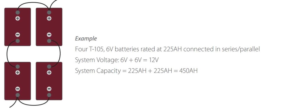
Below we are going to connect two strings of series batteries, and connect them in parallel.
The top pair are wired in series = 225AH, 12V — this pair is called a string
The bottom pair are are also wired in series = 225AH, 12V — this pair is called a string
Now we will connect each string in parallel, where the voltage stays the same, and the amp-hours are added up giving us a large 12V battery bank of 450AH
Before the advent of LiFePo4 deep cycle batteries it was common, as I did, to use 6 volt lead-acid golf cart batteries. These are designed for heavy duty use and frequent recharging. Plus just about everything about them is recyclable and, more importantly, they are usually recycled. We haven’t got to that point with the different types of lithium batteries.
With the prices of LiFePo4 lithium batteries dropping significantly over the past few years it just make more sense to use LiFePo4 batteries for these kinds of off-grid solar systems.
Large RV Solar System Example
Measure Electric Use
Here we will assume the RV averages 40 Amp-Hours of consumption each day. That comes out to 1.67 amps per hour over a 24 hour period.
To make these measurements a battery monitor that can measure amp-hours is needed. You should include one in a solar system install, so just buy one first for your measurement step.
In my 20 Year Review of the Trimetric Battery Monitor, I explained how a shunt-based battery monitor records the amount of energy sent to the battery and how much energy is removed from the battery to power the consumers in the RV.
Without accurate knowledge of how much energy is being used on a daily basis, it is difficult to estimate what size solar system is needed. The ability to measure usage will help design a system that is neither too small, nor too large.
Determine Needed Power Storage Requirements
Once we know how much power the RV consumes, the next step is to determine how many days worth of reserve storage capacity is desired — that is, if it rains for 5 days you won’t be able to recharge the battery.
For our example we will use 5 days of storage capacity as our planned capacity.
Using a bit of math, the minimum size battery would be:
40AH per day TIMES 5 days
40 X 5 = 200AH battery capacity
If a 200AH battery is purchased, it creates a problem where after 5 days the 200AH battery would be completely dead. The other consideration is what type of battery chemistry to purchase.
Conventional Lead-Acid Batteries
When a lead-acid battery is 50% discharged its voltage will be right around 12 volts. Some 12 volt powered devices in an RV don’t work well when the voltage drops below 12.
Additionally, continued charge cycles at less than a 50% state of charge will lead to a shorter battery life. For lead-acid batteries it is recommended to size the battery so it doesn’t drop below 50% of its capacity — this will provide the best mix of battery life and cost.
For this example let’s change our term Storage Capacity to Useful Storage Capacity. If we want to avoid dropping below a 50% state of charge, we will need a
400AH Capacity Battery (lead-acid)
Several possible configurations for a 400AH battery bank:
- A single 400AH 12 Volt battery
- Two 400AH 6 Volt batteries
- Two 200AH 12 volt batteries
LiFePo4 (Lithium) Batteries
When a LiFePo4 battery is 50% discharged its voltage will be around 12.8 volts. It doesn’t drop down to 12.0 volts until about 91% of the battery capacity has been used. LiFePo4 can handle many more charge cycles than their lead-acid counterparts.
As with lead-acid batteries, options are a single battery or series, parallel, or series/parallel configurations.
However, just like lead-acid batteries, the less of the capacity that is used between recharging, the longer the battery will last. For this example, a 300AH LiFePo4 battery will work well.
300AH Capacity Battery (LiFePo4)
Optimum Battery Charging Rates
This isn’t a topic I addressed in Part One. The optimum charge rate for conventional or LiFePo4 batteries is 20% of its capacity.
LiFePo4 batteries can often handle much higher charge rates and many manufacturers recommend somewhere between 20 and 50 percent of the battery capacity, with 20% providing the longest life expectancy for the battery. Typically LiFePo4 batteries can be charged at 100% of the capacity rating, but at the expense of a shorter life.
For Lead-Acid batteries the rate is usually 20 or 30 percent of capacity.
The recommended charge rates are indicated by a “C” for capacity. A 20% charge rate would then be designated as:
0.2C
The table below shows the recommended charge rates for the two types of batteries.

The next table highlights how long it would take the recharge a battery with a 20% charge rate. Remember that we need to but back 200AH into our battery bank after 5 days of rain for our RV solar system example. I must point out that in winter, when the sun is low and if the solar panels are not tilted for the angle of the sun above the horizon, the system cannot deliver the maximum current.

For the lead-acid battery (400AH), the optimum charge rate will require a 33% larger solar array than the size solar array needed to charge the smaller capacity (300AH) LiFePo4 battery.
Table #2 above provides us with valuable information to size our solar array.
What Size Solar System?
Calculate Solar Array Size
In my article, Solar Charge Controllers — PWM vs. MPPT, I stated that for solar systems of around 600 watts or larger it makes sense to go with a MPPT solar charge controller, so we won’t do any calculations for PWM controller for this exercise.
We also discussed (with math) how to calculate how much energy a MPPT controller can get from a solar array by using Watt’s Law.
We will still use Watt’s Law, but we are searching for Amps. Using the formula
Watts = Voltage X Amps
Since we know the amps we need, for a MPPT controller we just multiply Amps by the Solar Controller’s Charge Set Point, which is usually set at 14.6 volts. Thus we get:
(for our 300AH LiFePo4 battery) Watts = 14.6 volts X 60 amps
14.6 X 60 = 876 Watts
(for our 400AH lead-acid battery) Watts = 14.6 volts X 80 amps
14.6 X 80 = 1168 Watts
It is going to make sense that we should opt for the 300AH LiFePo4 battery for most intallations. The battery will last longer, provide more voltage, and require a much smaller solar array — 25% smaller than a system with a lead-acid battery.
Remember that this is what would be required to put 200AH (5 days of no sunshine) back into our battery bank. If we opted for a smaller Useful Storage Capacity, that is fewer days of stored capacity, then we could downsize the capacity or our battery and of our solar array. Hopefully I’ve provide an easy to follow method of doing this.
We also need to consider the Peak Sun Hours discussed in Sizing An RV Solar System: Part 1.
For my location in Palm Springs, California, which gets lots of sunshine compared to much of the US, we saw that the month of least Peak Sun Hours was December, and that if the solar panels were mounted flat on our travel trailer’s roof, we would get 3.01 hours of Peak Sun Hours. Looks like we’ll be a little short from our data in Table 2, which indicated we would need 3.3 hours to put all the amps back in.
Instead of charging at the optimum rate of 60 amps, our solar array will be charging at 55 amps, which is the difference between what a 876W array would produce versus our 800W configuration. Our charge rate will be 0.183C versus 0.2C, which is fine.
On the other hand, we would probably get our battery bank up to 100% full capacity early the next day, unless it rained again all day. I must also point out that if you have a battery monitor, you can use it to help monitor battery use, and conserve some power during those days of really poor weather.
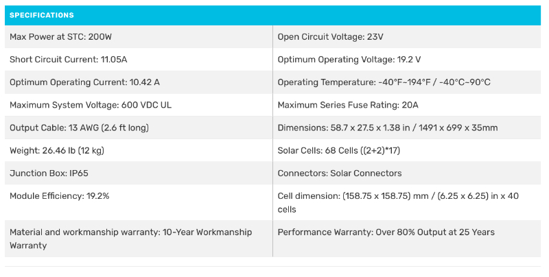
For our example RV Solar System we’ll use 800 Watts of solar using four Renogy 12V 200W solar panels. Here are the specifications for these panels:
Calculate Solar Controller Size
Morningstar String Calculator
Morningstar Corporation has an online calculator for determining which of their solar controllers will work with different solar arrays. This string calculator is a great tool and there is no guessing which of their solar controllers will be compatible with any given array of solar panels. Here’s the link to the Morningstar String Calculator.
You can choose a solar panel from a drop-down box, or if they don’t list a particular panel that panel’s specifications can be entered manually.
After all the data for the panels is entered, the battery’s minimum and maximum voltages, the lowest expected ambient temperature along with the average high temperature, you can pick any of Morningstar’s solar controller and the program will show whether it is compatible and with how many panels.
45A MPPT Charge Controller Calculations
After entering all this data, I picked a Morningstar TriStar 45A MPPT controller. The
String Calculator indicated that the TriStar 45 MPPT would be an optimal choice for 600W (3 panels), but with 800W (4 panels) the solar array would be over-sized for the controller and probably would not deliver the full potential of the solar array. See the screen shot below (click on image to see full size in a new window):
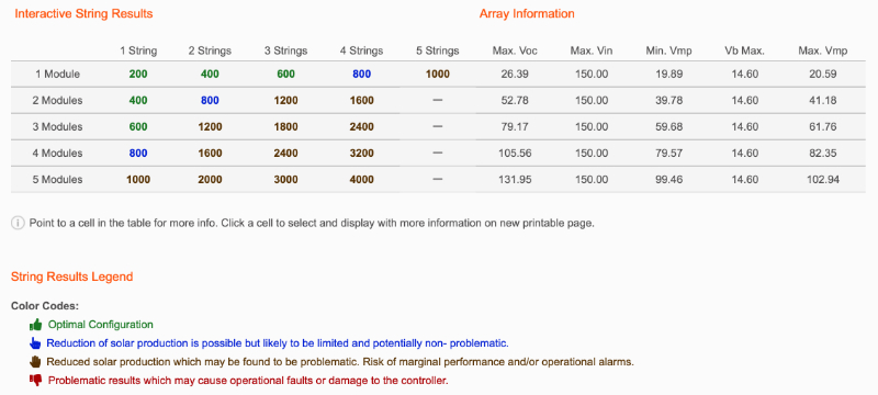
The table shows the number of panels wired in parallel in the top row, and the number of panels wired in series in the first column. Yes, just like batteries, solar panels can be connected in series, in parallel, and in series-parallel (more on this later).
60A MPPT Charge Controller Calculations
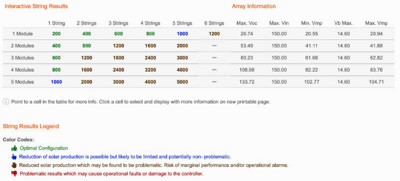
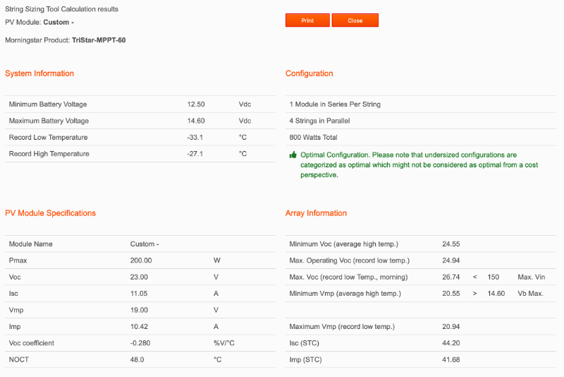
Since we probably won’t get full potential power with the 45A MPPT controller, I ran the calculator again picking a TriStar 60A MPPT solar charge controller. The results state that this controller is optimal for our 800W system (4 panels) wired in series or in parallel.
60A MPPT Charge Controller Series Report
When using the String Calculator you can click on any of the strings for more detailed information. Clicking on the 800W solar array in Series link, this report is generated:

60A MPPT Charge Controller Parallel Report
And below is the report for the 800W solar array in Parallel report link.
This information on series and parallel configurations will be very important when we decide how we want to connect the panels, and we will find one of these options to generally be better than the other.
So far, we have determined, based on averaging 40AH per day that the optimal system would be:
- 300AH LifePo4 battery
- 800W solar array
- 60A MPPT solar controller
Now we are going to need to purchase a bunch of stuff to install it!
Materials List
Wiring Solar Panels in Parallel
Earlier we looked at the different ways to connect batteries in strings: series, parallel, or series-parallel.
We can do the same thing with solar panels. There are a couple of reasons for doing this and we will find that:
- Panels wired in parallel require more components
- When wiring in parallel we add the amps of each panel, which can create the need for some pretty thick wires and add complexity.
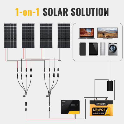
Below is a diagram of our four 200W solar panels wired in parallel and connected to a MPPT charge controller.
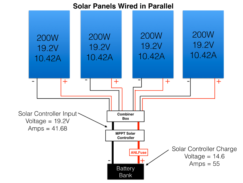
Each panel has a specification of 10.42 amps output. We need to add up the amp rating for each panel to determine how many amps will reach the controller.
10.42 amps X 4 panels = 41.68 amps
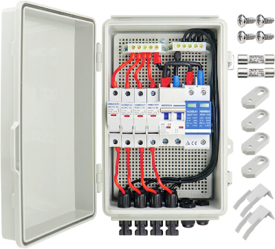
We will connect all the positive leads together and all the negative leads together. Instead of using the common solar Y-connectors, we need to use a combiner box to combine four pairs of wires from the solar panels into one pair of wires to the solar controller.
This is because our 41.68 amp current exceeds the standard Y-connector specification.
By the way, you probably noticed that 41.68 amps are going into the solar controller and 55 amps are moving from the controller to the battery. As we discussed in the MPPT vs PWM article, a MPPT solar control can modulate both voltage and current to maximize all the energy produces by an array of solar panels.
The amount of amps that is output from the controller is calculated with Watt’s Law:
Watts = Volts X Amps
Amps = Watts ÷ solar charger set point Volts
Amps = 800W ÷ 14.6V
Amps = 54.79
In this parallel setup, we need to run the four pairs of solar panel leads to a combiner box, where we will connect them to a single pair of wires capable of handling 55 amps to the solar controller. This wire-pair comes out of our combination box and goes to the solar controller. It is usually easiest to mount the combiner box on the roof, and run the single output wire-pair down to the solar controller that is located near the battery bank.
Otherwise, we would need to run 4 pairs of wires across the roof and down into the combiner box. the two output wires.
Remember that we want the solar controller as close to the battery as possible.
Our wire-pair of output wires from the combiner box need to carry 41.68 amps, which is why we need a combiner box and not standard “Y-Connectors.” I’ll explain.
Solar Y-Connectors
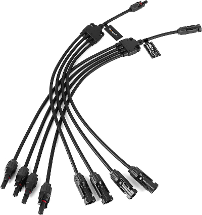
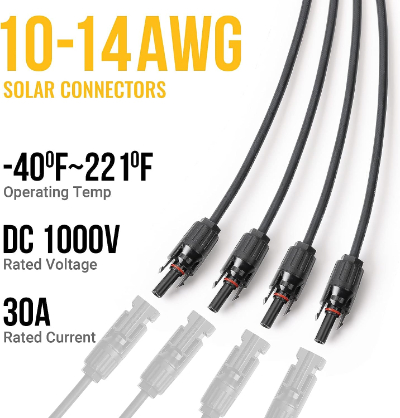
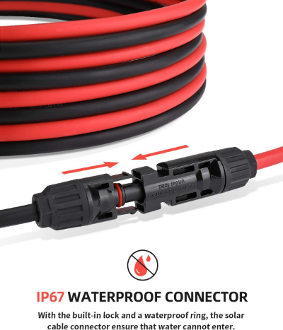
On smaller systems where the solar panels are wired in parallel, standard Y-Connectors are typically used. These connectors can combine several positive wires together and several negative wires together. They use the standardized water-proof connectors that are also found on the solar panel leads, making it quick and easy to connect solar panels in parallel.
The problem is that the maximum amperage Y-Connector sold is only rated for 30 amps. Our solar system will carry 41.68 amps, which is too much for the connectors. So we need to use a special combiner box.
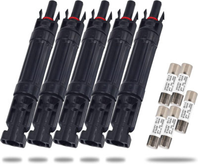
Also, when wiring solar panels in parallel, each panel needs a fuse. The combiner box contains fuses or circuit breakers for each panel’s wiring. With a smaller system where the Y-Connectors can be used, an inline fuse should be placed in every Positive (+) coming out of each solar panel.
Below are some pictures of Y-Connectors for reference:
In-line Fuse Holder for Each Panel (Parallel Connections)
To determine the fuse size, the solar panel should have a “Maximum Series Fuse Size” and for our panels the specification is 20 amps. Yes, it says “Series” but this is the size inline fuse we want to use in a Parallel setup.
This link will provide the particulars of the 20A inline fuse shown below.
Combiner Box
Below is a picture of a combiner box, and the information is linked here. I haven’t used this box, so it isn’t a recommendation. It is waterproof, which is important when mounted outside. I share this so it is easier to visualize what a combiner box is.
Determine the Proper Wire Gauge
It isn’t unusual to have a length of wire from the combiner box to solar controller that is 20 or 30 feet long. So we need to calculate or look up the proper gauge wire that can carry over 40 amps from the combiner box to the solar controller.
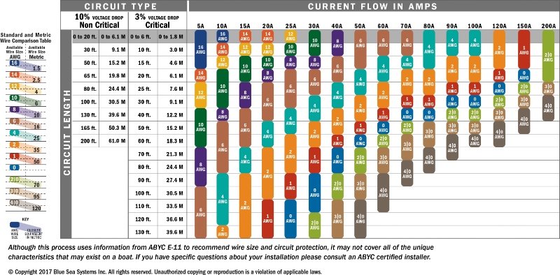
Below is a table from Blue Sea Systems:
We need a 30 foot run of wire that can carry over 40 amps with 3% or less voltage drop. Since our amps out will be a little over 40 amps, we need a cable that can carry 50 amps.
Cross referencing the chart we find that a 2AWG wire is needed. 2AWG isn’t a wire, it’s a cable. A very thick cable — like bigger than the battery cables in my 2020 Ford F-250 Super Duty. Plus since it is on the roof we need the cable to have a UV protection coating or run it inside of conduit.
Lucky for us, since we are using a MPPT controller, there is an easier way.
Wiring Solar Panels in Series
Below is a diagram for wiring our four 200W solar panels in series.
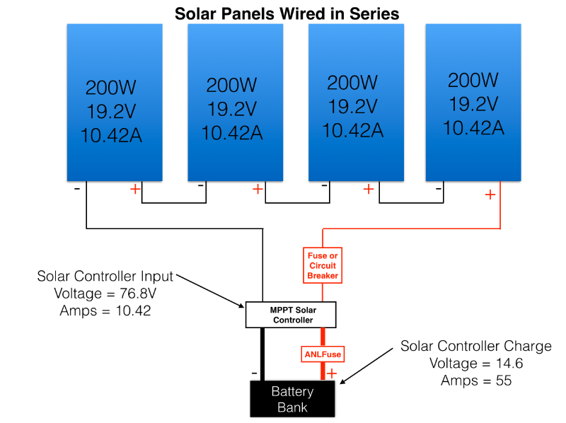
When connecting solar panels in series, we add up the volts for each panel and the amperage will remain the same. For this example the panels wired in series will output 76.8V and only 10.42 amps. If the panels are oriented in such a way that we need extensions to connect the solar panel leads together, it won’t require thick wires since our panels only have an output of a little over 10 amps. We can use 12 or 14 gauge extension wire connectors. The remaining positive and negative wire at each end of the array can be connected to a 30 foot 10 or12 gauge extension pair.
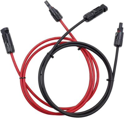
An example is this short 12AWG extension cable pair with each being 5 feet long:
Below is a 40 foot pair of 12AWG extension cables that would be used to connect the remaining negative and positive cable from the solar panel array to the fuse or circuit breaker on the Positive (+) and the Negative from the array to the solar controller..
With series wiring we won’t need the individual fuses for each panel as required in a parallel-connected array. We should use a Circuit Breaker Panel and this will be discussed shortly.
Panels in Parallel vs Series, Pros and Cons
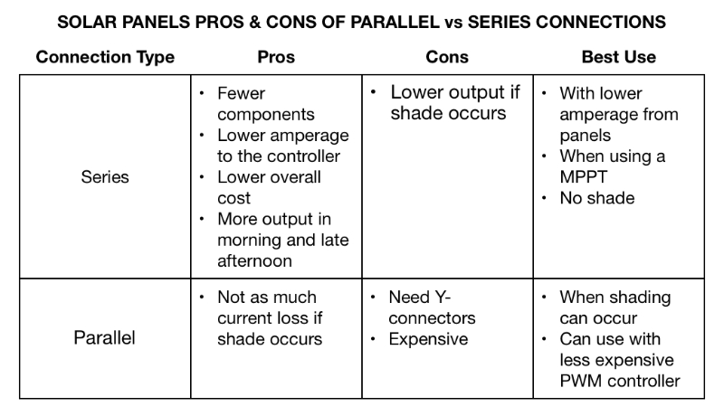
Using an array connected in parallel is mostly used for smaller systems, most often with PWM controllers. As we saw, panels in parallel increase the amps and keep the voltage the same.
As demonstrated parallel systems with high amperage will require some very thick wires. Along with thick gauge wires, parallel need extra components such as Y-connectors or a combiner box.
Shade
Should shade hit one of the panels, parallel panels will lose less power than those connected in series. In a series connection, if there is shade on one panel, the current will drop and the current will take the lowest value in the string. This is because in series connections, the current stays the same but the voltage is added together.
On the other hand, if shade hits one parallel panel we won’t lose as much current because in parallel connections the voltage stays the same but current is added together.
Solar Cable Polarity
This is really, really important!
Most panels don’t come with color coded wires. Both the Positive and negative leads are black. Usually there is a tag on each cable indicating whether it is positive or negative, but I have read stories where the labels were reversed and install caused damage to the system.
A Best Practice is to check the polarity with a Voltmeter. Light will need to be shinning on the panel so it can generate electricity. Connect the leads from the voltmeter to each panel wire.
If the voltmeter reading is positive, the voltmeter’s positive lead is connected to the solar panel’s positive wire.
If the voltmeter reads negative volts, the voltmeter leads are reversed — meaning the voltmeter’s positive lead is connected to the solar panel’s negative wire and the voltmeter’s negative lead is connected to the solar panel’s positive wire.
Solar Cable Connector Markings
Each waterproof connector on solar cables has a positive (+) or a negative (-) marking. These have nothing to do with polarity. The markings indicate whether the connector is a male or female plug.
Circuit Breaker Panel
We can use a single circuit breaker in between the solar panel wiring and the solar controller (this is required by most electrical codes). With a circuit breaker, it will be easy to disconnect the solar panels if we need to do repairs or troubleshooting.
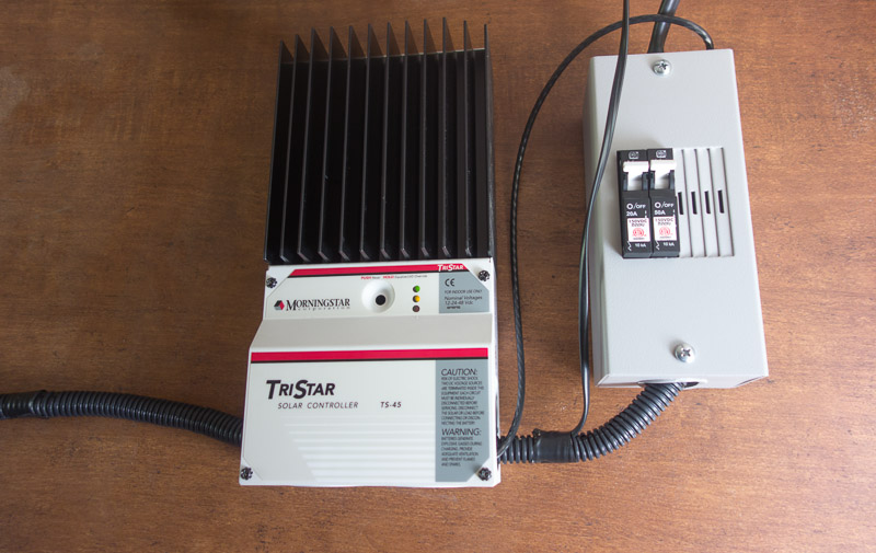
There are two circuit breakers in the circuit breaker panel above. One connected from the solar array on one side; the other side of the circuit breaker goes to the solar controller.
The other circuit breaker connects the solar controller output to a battery cable that goes to the battery bank. The panel box shown can hold 4 breakers. This allows for future expansion of the system, which I did upgrade this year.
Here’s a diagram of the circuit breaker and the solar charge controller:
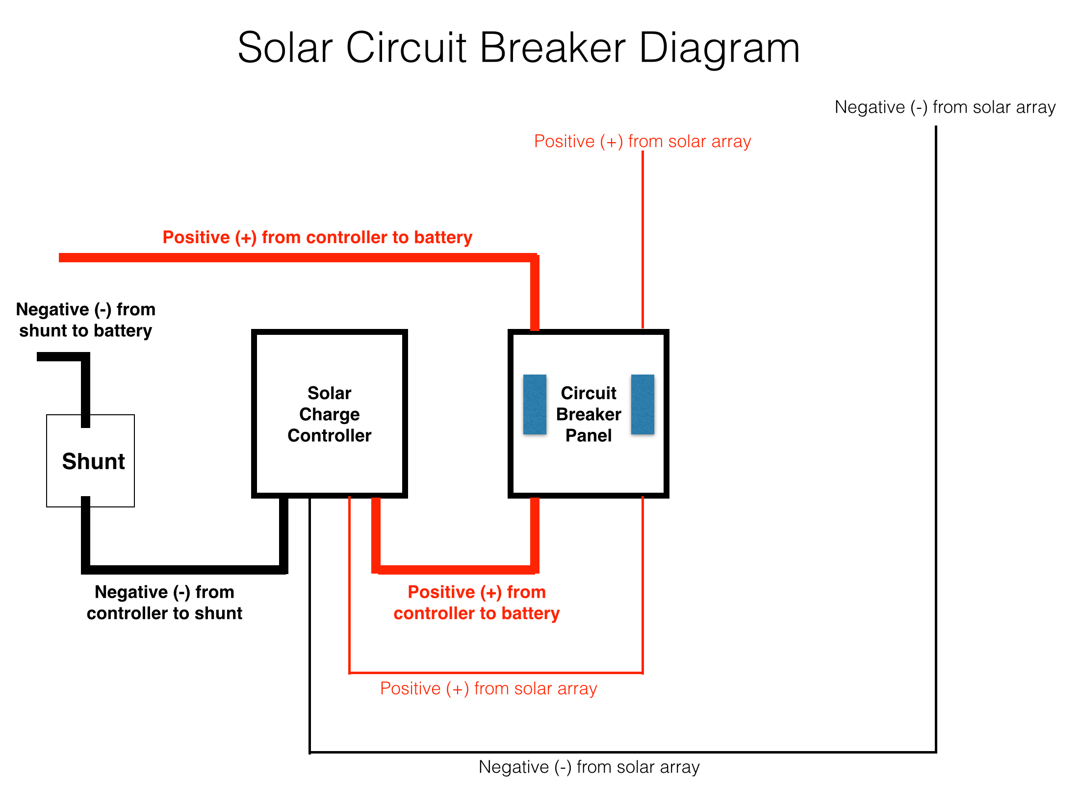
Circuit breakers must be designed for Direct Current (DC) systems. You cannot use regular household circuit breakers.
Since our panel array is outputting just over 10 amps, we want a circuit breaker that is about 25% higher, which means a 15A circuit breaker from the Solar Array Output to the Solar Charge Controller Input.
Our solar controller is rated at 60 amps and the controller will be charging our battery bank with around 55 amps (as we calculated earlier), so we want a 60A circuit breaker from the Solar Controller to the Battery Bank.
With our solar controller outputting close to 60 amps, we need to size the cable for 60 amps. Using the Blue Sea Systems wire chart again, we see that a 6AWG battery cable will handle up to 60 amps over a maximum of 6 feet with 3% or less voltage drop. We will also need the same size cable to connect the negative side to the shunt terminal of our battery bank.
I use products made by MidNite Solar. The boxes come without circuit breakers allowing the purchase of separate circuit breakers of different amp ratings. Details on the MidNite Solar Baby Box can be found here.

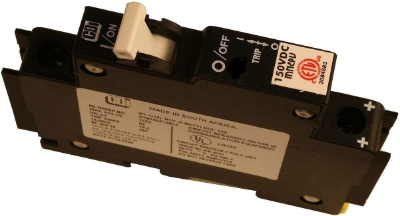
Details for the MidNite Solar circuit breaker that fit the Baby Box can be found at these links:
Z Brackets for Mounting the Panels
The most common method of mounting solar panels to the roof of an RV is to use Z Brackets. These brackets will position the panels above the roof for air flow. I like the Renogy Z brackets over the other types I have used over the years.
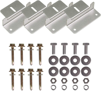
Each package comes with 4 brackets and mounting hardware. Nuts, washers, and bolts to attach the brackets to the bottom rail of the solar panel. Each panel has several pre-drilled holes in the frame rails and the bolts fit perfectly. The kid also comes with four self-tapping screws for mounting the brackets to the roof.
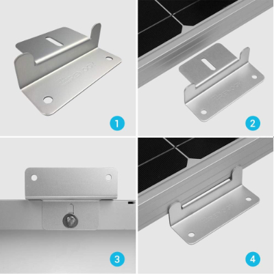
Once the panels are mounted, you will want to apply a liberal amount of Dicor Self-Leveling Lap Sealant. This is amazing stuff. After application it will slowly level out filling any nooks and crannies. We haven’t had a single leak from our solar system install over 10 years ago. Most RV manufacturers use Dicor to seal roof vents and skylights. Dicor comes in several colors.

Make sure you get the self-leveling lap sealant because Dicor also sells non-leveling sealant.
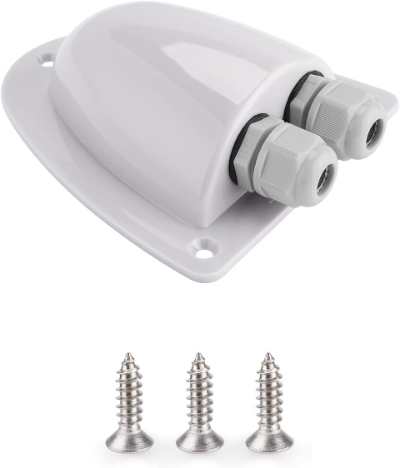
Roof Gland
The last thing on the roof to be completed is to run the wires from the roof down to the solar controller. Finding a way to get the wires down into the RV can be challenging. Some owners run the wires down along vents or other existing pathways. Then route their wires to the solar controller.
However you want to route your wires, always try to run them the shortest distance possible to avoid voltage drops. Because of this, I have always used outdoor electrical boxes.

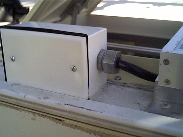
These have worked out well for me. If I were to do a new rooftop install, I would take a serious look at the roof gland products that have come to market since the time I did our three different solar system installations, such as this one.
Shopping List
Now that we have covered all the aspects of a larger RV solar system from measuring the power usage, determining how much usable battery storage capacity is needed, and calculating the solar array size needed to match the usage and battery capacity, here is a list of the items covered. It is just a summary of all the components covered in the article for our example 800W solar system.
I have also included links should you want more details and prices for any item. Most of the items are products I have used and am completely satisfied with. Others I haven’t used but are highly rated.
Measure
Storage
We have been using a JITA 300AH LiFePo4 battery for 18 months and have been very happy with it. Here’s the initial review of it.
Another option is the highly rated LiTime 300AH LiFePo4 battery
Harvest the Sun
Renogy solar panel mounting Z Brackets
Dicor Self-leveling Lap Sealant
5 foot 12AWG solar panel extension cables
30 foot 12AWG solar panel extension cables
MidNite Solar 15A circuit breaker
MidNite Solar 60A circuit breaker
Morningstar TriStar 60A MPPT Solar Charge Controller
Morningstar TriStar 60A MPPT Solar Charge Controller with Display
Morningstar Remote Display for TriStar Charge Controllers
6 gauge battery cable pair from controller – Positive (+) to battery and Negative(-) to Shunt
6 gauge Negative (-) cable from shunt to battery negative
Read all parts of the Sizing an RV Solar System series:
