How Much Power Will Your Solar System Actually Harvest?

In Part One and Two of this series we discussed how to measure how much energy is used daily, how to determine needed power storage (what size battery bank), and how to size the solar array.
This post (Part 3) will take a look at all the components and conditions that impact how much solar power will actually be generated. This is the final step to see how the previous calculations will really work for a real world RV solar systems. First we need to define some terms.
This post in a continuation of:
Sizing An RV Solar System: Part 1
Sizing An RV Solar System: Part 2
Solar Charge Controllers: MPPT vs PWM
Watts versus Amps
If you take a look at your monthly household electric bill from your utility company, everything is stated as kilowatt hours. But for our RV system we have been discussing amps more that watts — this is because we are storing our excess power in a battery bank.
So, let’s define some terms:
Watts: A watt is a unit of power that measures the rate of energy transfer — This can be defined as the overall working capacity of the electrical energy.
Amp: how much electrical energy is being supplied through a particular electrical line.
Our house utility bill says nothing about amps, because the electrical company charges for how much energy is delivered to the residence. (We haven’t paid an electric bill in over 3 years because we have a solar system).
Inside the house we need to pay attention to how many amps certain appliances consume. An example is our garage. The electrical circuit in the garage can only supply 15 amps. That is, the circuit breaker and wires can only deliver 15 amps. If I connect our travel trailer to an electrical outlet, and then turn on the RV air conditioner on a hot day, the garage circuit breaker will trip. This is because the air conditioner can consume over 20 amps.
Same goes for our kitchen. If we try to run the microwave, an air fryer, a toaster oven, and a blender all at once, the appliances will draw more than 20 amps and the 20 amp circuit breaker will trip.
Watt-Hour (WH): how many watts have been delivered in one hour.
Amp-Hour (AH): how many amps have been supplied via an electrical line in one hour.
Kilowatt (kW): 1,000 watts.
Kilowatt-Hour (kWh): 1,000 watt-hours.
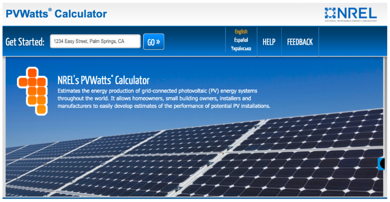
PVWatts® Calculator
This is a tool on the NREL Website, which is a national laboratory of the U.S. Department of Energy, Office of Energy Efficiency and Renewable Energy.
The website states that NREL’s PVWatts® Calculator “estimates the energy production of grid-connected photovoltaic (PV) energy systems throughout the world. It allows homeowners, small building owners, installers and manufacturers to easily develop estimates of the performance of potential PV installations.”
It is used for grid-tied solar systems — meaning the output of the solar systems is connected to the power utility — not a battery bank. We can use the tool for an RV because everything is measured in Watts.
Our Example RV Solar System
From Part Two of this series we will continue to use the components calculated that included:
- 300AH LiFePo4 Battery
- 800 watt solar array (four 200W panels)
- MPPT Solar Charge Controller
Since we will be using Watts for our calculations, we need to find how many watts are stored in our 300AH battery bank. Using Watt’s Law, we come up with this:
Watts = Amps X Volts
or
Watt-Hours = Amp-Hours X Volts
Watt-Hours – Amp-Hours X (Nominal Voltage of the LiFePo4 Battery)
Watt-Hours = 300AH X 12.8 Volts
Watt-Hours = 3840 wH
PVWatts® Calculator Guide
Step 1: Enter Your Address

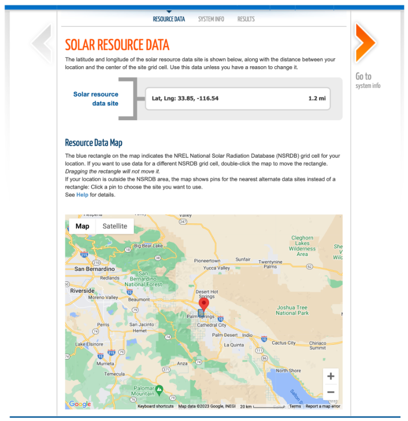
After entering your address Click the “GO” button, which will show your location on a map for verification that the tool has located your actual address.

Confirm your location, then Click the “Go to system info” button at the upper right.
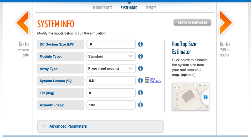
Step 2: Enter System Information

DC System Size (kW):
Our solar system is Direct Current (DC) and we have four panels totaling 800 watts. The input box is for kW (kilowatts). So we simply divide 800W by 1,000 and get 0.80 kW.
Module Type:
Most solar panels have an efficiency of between 19% and 20% so choose “Standard” from the drop-down menu. The specification for the Renogy 200W solar panels is 19.2 percent.
Array Type:
Our panels are roof mounted.
System Losses (%):
With any solar array there are points where watts (or current) can be lost. We’ll cover those shortly.
Tilt (deg):
This is the angle the panels are tilted. Since our RV panels will be mounted on the roof horizontally, we’ll choose 0° tilt. Some people build or buy special mounting racks that can be tilted, which means you have to get on the roof to tilt the panels manually.
If one wanted to be high tech a motorized system could be designed and installed. This would mean the RV would need to be orientated so the panels face south, which is the next item to set up in the System Info screen.
Azimuth (deg):
180° is south. Our panels are mounted horizontally and will always get the same amount of sun no matter what direction the RV is parked.
System Losses (%):
There are several things that contribute to system losses. The default value is 14% but the PVWatts Calculation Tool has a “Loss Calculator” to make it easier to review how the 14% was calculated and to make changes.

Soiling
“Losses due to dirt and other foreign matter on the surface of the PV module that prevent solar radiation from reaching the cells. Soiling is location- and weather-dependent. There are greater soiling losses in high-traffic, high-pollution areas with infrequent rain. The default value is 2%. You can use monthly irradiance losses for losses that vary by month instead of including soiling in the system losses.”
With an RV I find it quick and easy to clean the panels. The default value is 2% and I set this cell to zero.
Shading
“Reduction in the incident solar radiation from shadows caused by objects near the array such as buildings or trees, or by self-shading for modules arranged in rows when modules in one row cause shadows on those in an adjacent row. The default value of 1% represents an array with little or no shading. Shading analysis tools can determine a loss percentage for shading by nearby objects.”
The default value is 3% and I set it to zero. Another failure on RV systems, where the panel(s) are located close to other things on the roof (vents and/or an air conditioning unit) that are often casting shadows on the panels.
Snow
“Reduction in the system’s annual output due to snow covering the array. The default value is zero, assuming either that there is never snow on the array, or that the array is kept clear of snow. You can use the monthly irradiance losses to represent snow loss instead of including it in the system losses.”
I left the default value. If it snows we aren’t going or staying!
Mismatch
“Electrical losses due to slight differences caused by manufacturing imperfections between modules in the array that cause the modules to have slightly different current-voltage characteristics.”
The default value of is 2%. I left the default value.
Wiring
“Resistive losses in the DC and AC wires connecting modules, inverters, and other parts of the system.”
The default value is 2%. I left the default value. This is important. I have seen so many systems that underperform because of wrong gauge wires.
Connections
“Resistive losses in electrical connectors in the system.”
The default value is 0.5%. I left the default value. This is also important. I have seen so many systems that underperform due to poor connections.
Light-Induced Degradation
“Effect of the reduction in the array’s power during the first few months of its operation caused by light-induced degradation of photovoltaic cells.”
The default value is 1.5%. I left the default value.
Nameplate Rating
“The nameplate rating loss accounts for the accuracy of the manufacturer’s nameplate rating. Field measurements of the electrical characteristics of photovoltaic modules in the array may show that they differ from their nameplate rating. A nameplate rating loss of 5% would indicates that testing yielded power measurements at Standard Test Conditions (STC) that were 5% less than the manufacturer\’s nameplate rating.”
The default value is 1%. I left the default value.
Age
“Effect of weathering of the photovoltaic modules on the array’s performance over time.”
The default value is zero. I left the default value. Most panels are warrantied to maintain 80% or more of their rated output for 20-25 years. You want to buy from a reputable manufacturer who will be in business for the next 20 years or so.
Availability
“Reduction in the system’s output cause by scheduled and unscheduled system shutdown for maintenance, grid outages, and other operational factors.”
The default value is 3%. In twenty years I have never had to shut the system down for these operational factors. I changed the value to zero.
For our example system the total loss with these adjustments is 6.81 percent.
Step 3: PVWatts Results
Click the “Go to PVWatts results” button.

AC Energy (kWh)
The calculator is for grid-tied solar systems, not an off-grid system that uses a battery bank to store the harvested energy. The AC Energy assumes an inverter is used to convert the DC watts into AC Energy and includes a 4% loss for the inverter. You could go back to the System Info page and subtract 4% for the losses. For this exercise I just left it as is.
Solar Energy Harvested Per Day
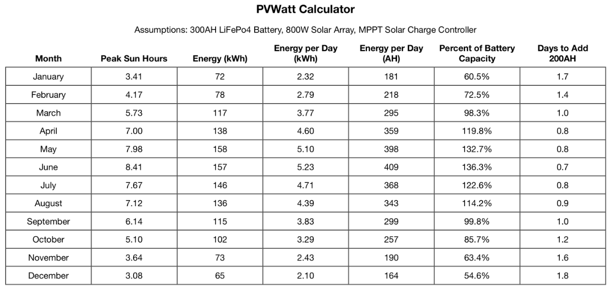
December has the smallest Solar Radiator (Peak Sun Hours) at 3.08 hours. The table above shows that for the entire month of December we should generate 65kWh of electricity. But we want to know how much per day. Some calculations follow:
65 kWh = 65,000 wH (watt-hours)
65,000 wH ÷ 31 days = 2,096 wH per day
Amp-Hours (AH) = wH ÷ battery bank nominal voltage
AH = 2,096 wH ÷ 12.8
AH= 163.75
163.75AH is 54.58% of our battery’s capacity. This begs the question of how many days of reserve capacity will our battery bank have if the weather turns really bad. In Part Two, our measure step indicated that we use 40AH of energy per day.
Since we have a LiFePo4 battery, we can use all of the stored 300AH of capacity without damaging it. If we run the battery down to less than 10% of its capacity it will shorten its life span.
In our example in Part Two, we wanted at least 5 days of reserve capacity or 200AH (40AH consumption X 5 days). That would leave us with 33% of our battery capacity.
If we can get 163.75AH back into the battery on Day 6, our battery will be charged back to 263.75AH, or about 88% of capacity (without considering any electrical use while charging the battery). On Day 7, assuming the weather is good, our battery bank will be fully charged. That’s pretty good!
Here’s a chart with each month:

The next and final article in this series will take a look at how I upgraded our 280W solar system, wired in parallel with a PWM Solar Charger, to a 880W system. I ended up with a hybrid system, so to speak. I didn’t necessary follow all the optimal suggestions, but it works really well. Stay tuned.
Read all parts of the Sizing an RV Solar System series: