Do Lithium (LiFePo4) battery deliver on the manufacturer’s claims. We’ll explore my 30 month experience, which didn’t live up to expectations. But there are some factors that need to be investigated as part of my conclusion. Then I’ll share me new LiFePo4 battery system for my remote telescope kit.
A couple years ago I shared my remote kit set-up for astrophotography. It included a Lithium (LiFePo4) battery bank consisting of three 16AH lithium batteries wired in parallel. I built this in April of 2021 and was my first experience with LiFePo4 batteries.
I had a concern that the LiFePo4 manufacturers’ claims of thousands of recharge cycles without losing more that 20% of capacity might be too good to be true. My concerns came true — after only 700 charge cycles or so, where my nightly use was less than 50% of capacity — the battery bank’s capacity is now only 43 percent!
A Cheap Battery Experiment
This section is long. I need to share all the steps I went through with the first LiFePo4 batteries I bought, plus the second three. This is mainly to reinforce buying quality products the first time. Also to document all the proper steps I went through.
So let’s start at the beginning. I bought three Miady 12.8 Volt 16AH LiFePo4 batteries in April of 2021. They were the absolute cheapest 16AH LiFePo4 battery on Amazon. The price was almost too good to be true, and I knew this wasn’t the best route to go. To be honest, it was more of a research project for me than a long-term investment.
Parallel Connections
When batteries are wired in parallel the voltage remains the same but the amp-hour ratings are added up. So three 16AH batteries will become a 48AH battery bank (3 X 16 = 48). But can this battery be wired in parallel? I don’t know because you cannot contact the company. They don’t have a website either. But most batteries can be wire in parallel using two or three batteries.
Testing Before Placing into Use
When batteries are shipped the US Department of Transportation requires batteries to be be charged no more than 50% of capacity, so I charged each battery using a quality regulated power supply set to 14.6 volts.

The high voltage cutoff worked all three batteries. The shut off voltage at 14.6 volts. I then completely discharged all three batteries and each of them shut off at 10 volts, which be their low cutoff point. The low cutoff worked on all three.
I again fully recharged all three. Each accepted a hair under 16AH and the fully charged voltage of each was equal to 1/100th of volt. All of this was excellent. I now connected all three in parallel and started using them as a single battery bank, using on average 22AH each night and recharging daily using my regulated power supply.
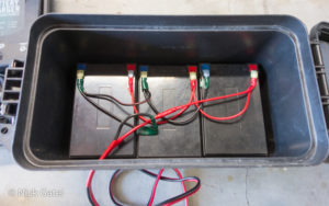
Three 16AH batteries (above) wired in parallel to create a single 48AH battery bank and are connected in standard configuration. The positive Red on the right goes to the charge port and the negative Black at the very left also goes to the charge port.
Battery box containing the three batteries are house in a plastic ammo/utility box.
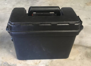
Battery Bank in Use
I used this battery bank almost every night for a 30 months charging it daily. After the initial charging and testing when they first arrived, I didn’t do any capacity testing. I had an inexpensive voltmeter mounted on the battery box and each morning after a nights use, the voltage would read between 13.1 and 13.2 volts. This was my first mistake — not using a real shunt-based battery monitor to track battery capacity — and I knew better after using a battery monitor for over 20 years on our solar systems installed on three different campers.
A LiFePo4 battery is at around 70% capacity at 13.2 volts and 40% capacity at 13.1 volts. That’s quite a spread and, as it turned out, the voltmeter I mounted on the battery box to monitor the battery voltage weren’t super accurate. And some nights I probably used a little more than 22AH.
Overall the battery bank seemed fine, with the voltmeter on the box always reading 13.1 or 13.2 volts. In fact, in 2022 I bought a second telescope mount and built a second battery box for the new kit.
When I built this second box the Miady batteries were no longer available, but a similar battery at a very low price was. So I bought three 16AH Fukuai LiFePo4 batteries. I went through the same preparation steps before connecting them in parallel.
Capacity Test
About a month ago the battery voltage of the original first battery bank was suddenly dropping down below 13 volts after night’s use. It was time to do a real capacity test as I outlined earlier.
The capacity test showed this battery bank was down to 43% of capacity. Testing the individual batteries after a full charge and resting overnight, all the voltages were equal within 1/100th of a volt with a quality meter.
Next I tested the newer bank of Fukuai batteries. They had over 300 charge cycles and were never discharged over 50% and everyday they were carefully charged at 14.6 volts. Capacity for this second battery bank of Fukuai batteries was already down to 78 percent.
Most manufacturers warranty LiFePo4 batteries to maintain at least 80% capacity for many years. Both these batteries had a 10 year warranty, but specifics were not stated in the description and no documentation came with either brand.
This isn’t a rant against either company. I knew from the outset that they were a risky purchase. Plus I gained a valuable education about LiFePo4 batteries.
Who Makes These Small 16AH Batteries?
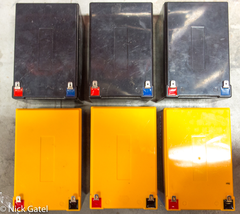
I suspect that both brands are “private labels” produced at the same factory for many different vendors.

Other than the design of the labels and the company name, the text is exactly identical. The colors of the cases are different but the mold markings terminal locations and terminals are the same too.
Battery Management System (BMS)
LiFePo4 batteries include a circuit board device called a BMS. The BMS manages the lithium iron phosphate battery packs inside the battery case. It can monitor individual cell voltages, temperatures, and the overall pack status. The BMS protects the batteries by preventing overcharge, over-discharge and short circuits. It also balances the cells and controls charging and discharging.
Most battery manufacturers purchase their BMS devices from third party vendors. Like anything else, there are high quality and also junk BMS devices. Given the price point of the six batteries I bought, the BMS is probably of low quality and who knows how they were programmed.
Anyway, it was time for me to get serious and purchase a high quality battery. But my experience with these small batteries raises the question,
“Are the charge cycle specifications for LiFePo4 batteries true or just marketing hype?”
The answer is, it depends upon who makes the battery.
Eighteen months ago I purchased a 300AH LiFePo4 battery for our travel trailer. In retrospect I should have done more testing with these small 16AH batteries — but it doesn’t matter — the large battery in our camper has worked fabulously — and I have been carefully monitoring it because it set me back $969 plus tax.
So I am convinced and an advocate of quality LiFePo4 batteries for deep cycle use.
LiTime 100AH LiFePo4 Battery
(This website may be compensated for linking to other sites for sales of products. As an Amazon Associate I earn a small fee from qualifying purchases at no additional cost to the purchaser.)
After a lot of research I settled on a single LiTime 100AH LiFePo4 battery to run both of my telescope rigs at the same time. After years of use, I know that together both rigs will consume around 44 amp-hours each night (22AH each).
For a detailed post on how I determined what capacity battery I needed, read this post on how to size a solar system where I outline the steps to
- determine the actual energy consumed by the devices you want to power
- determine the size battery to match those devices, with an eye to how often you will recharge them
- if if the battery will be connected to a solar array, how to size a solar system
For anyone putting together their first battery kit, the above post should provide much useful information to assist in the endeavor.
Right off the bat, after unpacking the LiTime battery, I was impressed with the detailed documentation package that came with it. It was now time to assemble the battery box and all the needed components.
Special Note About LiFePo4 Batteries
We’ve all read the horror stories about Lithium batteries exploding or self-igniting. These are not LiFePo4 batteries, but like all lithium batteries it is a lithium-ion battery.
There are six main types of lithium batteries:
- Lithium Phosphate (LiFePo4) — these are the batteries that are used as replacements for lead-acid batteries
- Lithium Cobalt Oxide
- Lithium Manganese Oxide
- Lithium Nickel Manganese Cobalt Oxide
- Lithium Nickel Cobalt Aluminum Oxide
- Lithium Titanate
LiFePo4 batteries have a little lower energy density, which is pretty much non-combustible. In addition to being safer than other lithium chemistries, LiFePO4 batteries have several advantages, especially for larger capacity applications like RV solar systems.
LiFePo4 batteries have a higher nominal voltage than their conventional competitors (12.8 V versus 12.0 V for their competitors). This means that when a LiFePo4 goes down to 9% of capacity it is still outputting 12 volts. A lead acid battery drops below 12 volts at 50% of its capacity. Thus you can effectively use all of the capacity to power things, while it is best to not let a lead acid battery drop below 50% capacity while is use.
LiFePo4 batteries can be fully discharged without damage. Another advantage is they perform better in cold weather below freezing. Whereas a lead-acid battery can lose 20% – 30% if its capacity the colder it gets. In the same conditions LiFePo4 will lose 5% – 10% depending on how cold it gets.
Don’t Charge a LiFePo4 Battery in temperatures below 32°F (0°C)!
Charging LiFePo4 batteries at temperatures below freezing will damage them. Some more expensive LiFePo4 batteries come with a low temperature cut-off that will not allow charging when the temperature drops below 32° F. If a battery manufacturer includes a low temperature cut-off they will specifically state so.
The specifications for each battery will include the charging information such as this from LiTime Batteries:
- Charge Temperature:0℃ to 50℃ / 32℉ to 122℉
- Discharge Temperature:-20℃ to 60℃ / -4℉ to 140℉
- Storage Temperature:-10℃ to 50℃ / 14℉ to 122℉
- Low-Temperature Protection:N/A
- Low-Temperature Charging Protection Auto Recovery:N/A
But some manufactures do not state whether or not the battery has low temperature protection. Buyers must exercise caution when shopping for a LiFePo4 battery. Cheaper brands use often use an inferior BMS for their batteries.
Earlier I posted a link to a LiTme 100AH LiFePo4 battery, which does not have a low temperature cutoff. LiTime does sell a 100AH LiFePo4 with low temperature cutoff and it costs about $60 more.
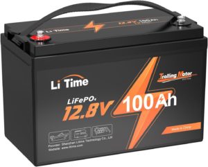
A better solution for some will be a self-heating battery. These batteries will raise the internal temperature high enough to be safely charged. Of course at a premium price. This LiTime 100AH self-heating LiFePo4 battery sells for around $100 more than their standard battery without a low temperature cutoff.

You probably noticed I am using LiTime products for comparisons. LiTime sells quality products at very competitive prices.
We rarely operate at temperatures below freezing. If the expected temperature falls below freezing, I simply disconnect the solar array from the battery bank. In our travel trailer I use circuit breakers, which makes it quick and easy.

With larger system, such as our camper, the solar controller needs to be connected to the battery when disconnecting or connecting the solar array and the circuit breakers make this simple.
The Battery Box
I had a spare Craftsman VersaStack toolbox in the garage from a couple 3-box stacked sets I had purchased for storing items in our travel trailer.
Turns out it was the perfect size for this project. I would need to drill some holes and make some cuts with a Dremel Tool.
A list of all the components follows:
- A real shut-based battery monitor was my first priority.
- A 100A 100mV shunt
- Two battery terminal post (positive and negative)
- Main battery cables
- Positive bus bar
- WAGO Lever Nuts
- 12V 10A Buck-Booster
- Power Pole connectors
- Power Pole panel mount
- Power Pole panel mount
- Double USB power outlet
- 12 Volt digital meter
- 12V power port
- Power Pole crimper
- A proper wire terminal crimper
- Wire terminal crimp ring connectors
- 16AWG Wire
- 12AWG Wire
- 12AWG inline fuse
- 10A ATC type fuse
Most of the items I was able to cannibalize from the old battery boxes. Anything extra I had in stock in my garage/workshop.
Below is the top of the box with everything in place. The Battery Monitor display isn’t very visible because of the angle of the camera.
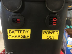
The Battery Charge port is a single Anderson PowerWerx (Power Pole) panel mount. I can charge the battery with a regulated power supply or a solar array.
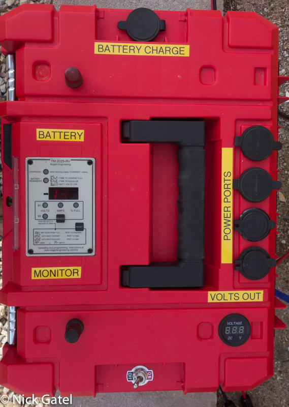
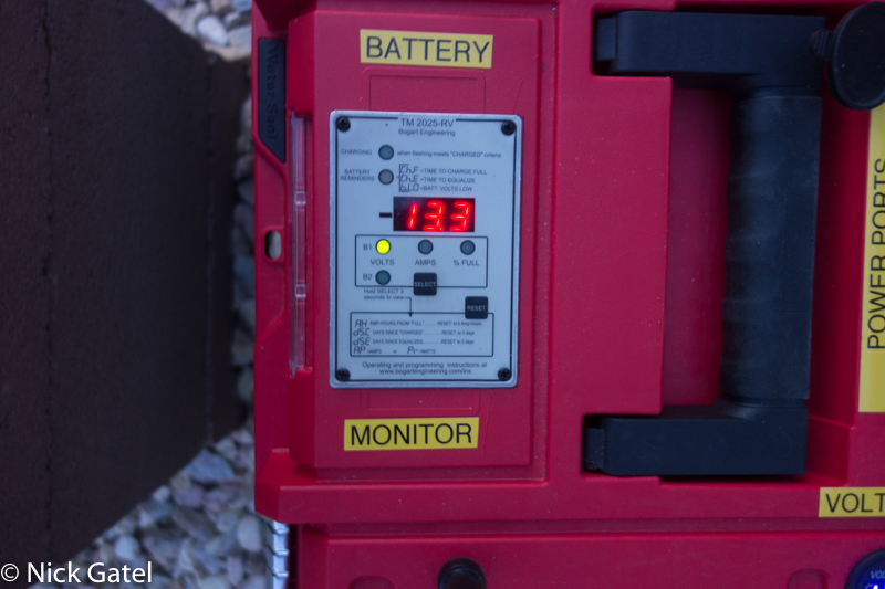

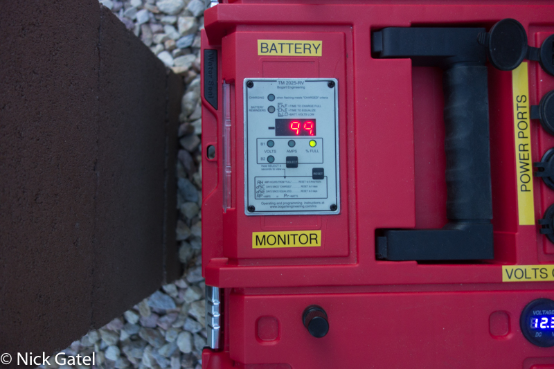
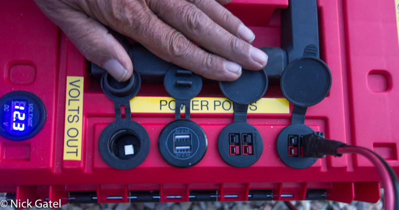
Battery Box Components
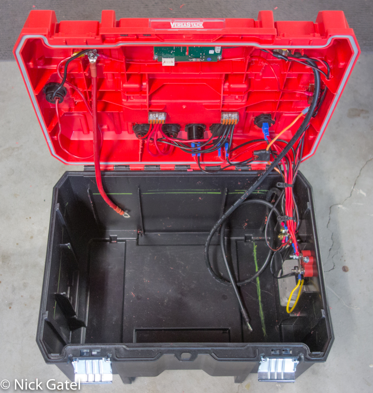
Battery Box Lid
I usually create a wiring diagram when building a project like this. I this case, I didn’t need to. Since I am lazy, I’m not going to create a wiring diagram just for this article, so I just added numbered circles, which I will key below.
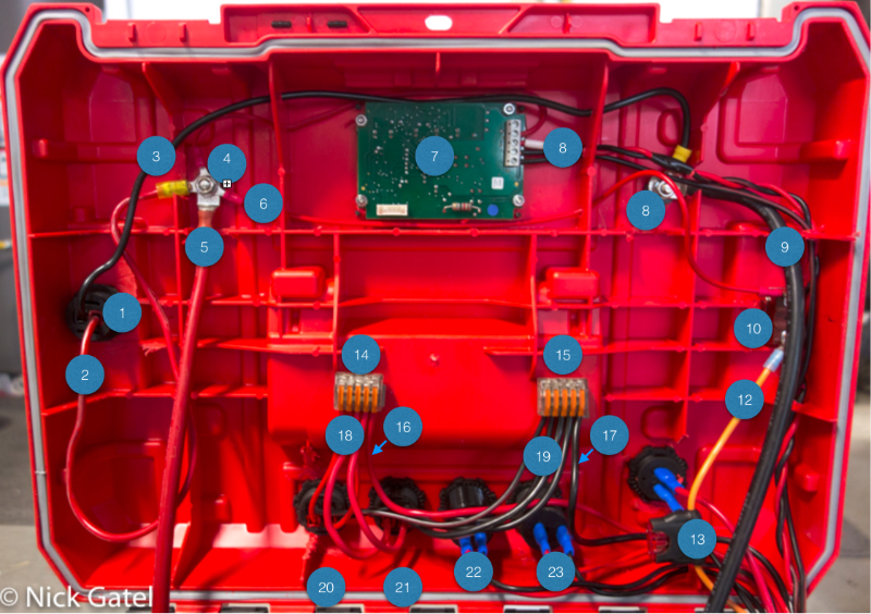
-
-
- Single Power Pole Panel Mount
- Positive wire to the Positive battery terminal post
- Negative wire to the Negative battery terminal post
- Positive battery terminal post
- Positive battery cable to the battery
- Positive wire to the ON/OFF switch
- TriMetric 2025-RV Battery Monitor
- Signal wires (4) from the TriMetric Battery Monitor to the 100A 100mV shunt
- Negative battery terminal post
- ON/OFF switch
- forgot to add #11 to the picture and am too lazy to redo it
- Power wire to the Buck-Booster input side
- 12AWG ATC inline fuse holder with 10A fuse
- WAGO Lever Nut for Power Pole dual panel mount (for + positive power out of the box)
- WAGO Lever Nut for Power Pole dual panel mount (for – negative out of the box)
- Positive power (+) from Buck-Booster output
- Negative power (-) from negative bus bar (bus bar not shown in this image)
- Four Positive Power (+) wires to the two Power Pole Output Panel Mounts
- Four Negative Power (-) wires to the two Power Pole Output Panel Mounts
- Double Power Pole Panel Mount for output circuits to one telescope kit
- Double Power Pole Panel Mount for output circuits to second telescope kit
- Double USB Power Port (black wire to Negative bus, Red wire to Positive bus — neither bus shown in image
- 12V Cigarette Lighter Power Port (black wire to Negative bus, Red wire to Positive bus — neither bus shown in image
-
Battery Box Interior
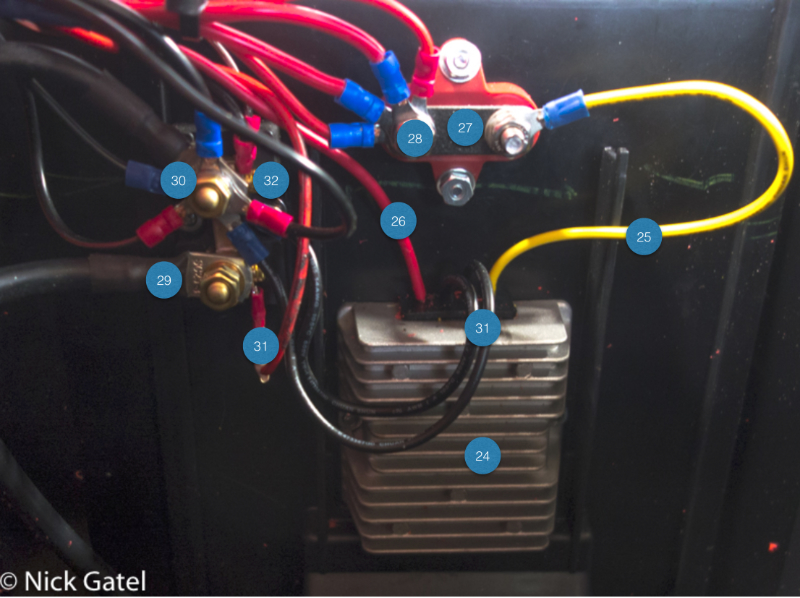
- Buck-booster
- Buck-booster Positive output
- Buck-booster Positive input from the ON/OFF switch
- Positive Bus Bar
- All Positive wires connected to Buck-Booster output (12.3 volts)
- Shunt connection to the Negative battery cable to the battery (it is the only connection on this side of the shunt)
- All negative connections for the entire system (the other side of the shut)
- Shunt Signal Wire connected to the Kelvin screw
- Shunt ground wires connected to the second Kelvin screw
Why am I using a 12 Volt Buck-Booster in 12 Volt System?
All electronics for both telescope kits run on 12 volts. In fact they are all happy from 12.0 to 13.8 volts. This includes the mounts, cameras, routers, and electronic focusers. But there is one exception — the two BeeLink GK-55 mini computers that control each kit. The computers are great up to 13.5 volts — much higher they simply shut down.
I run my systems all night while I sleep. At astronomical dawn the mini computer stops the mount motors and turns off the internal camera coolers. But everything is still powered on. If a solar panel starts charging, with a charge set-point of 14.4 – 14.6 volts (the charge specification for the battery) this high voltage will cause the computer to shut down, or worse, damage the computer. I have two identical 12 volt Buck-Boosters and though “rated” at 12 volts output, the consistently stay at exactly 12.3 volts. Perfect!
TriMetric Battery Monitor
The unit I installed was not designed to be panel mounted, it was part of a flush mount box. With a Dremel tool I was able to create a cut-out (for a very tight fit) and install the meter.
For more information about battery monitors and the TriMetric see my 20 Year Review of the TriMetric Battery Monitor.
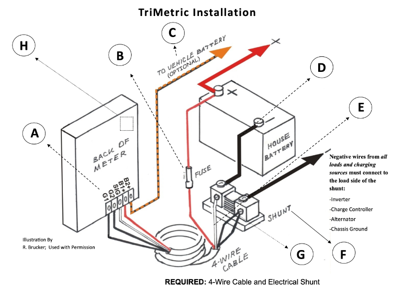
The illustration below will provide a better understanding of the Shunt connections to the TriMetric battery monitor.
Installing the Battery
I had to install the battery on its side in order for it to fit. With a LiFePo4 battery, this is an acceptable installation method.
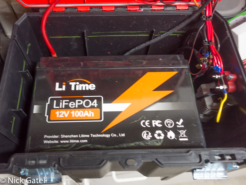
To keep the battery from shifting during transport, I filled some of the open space between the battery and the sides of the box with pieces of foam that came in the shipping box from LiTime.
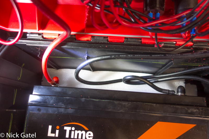
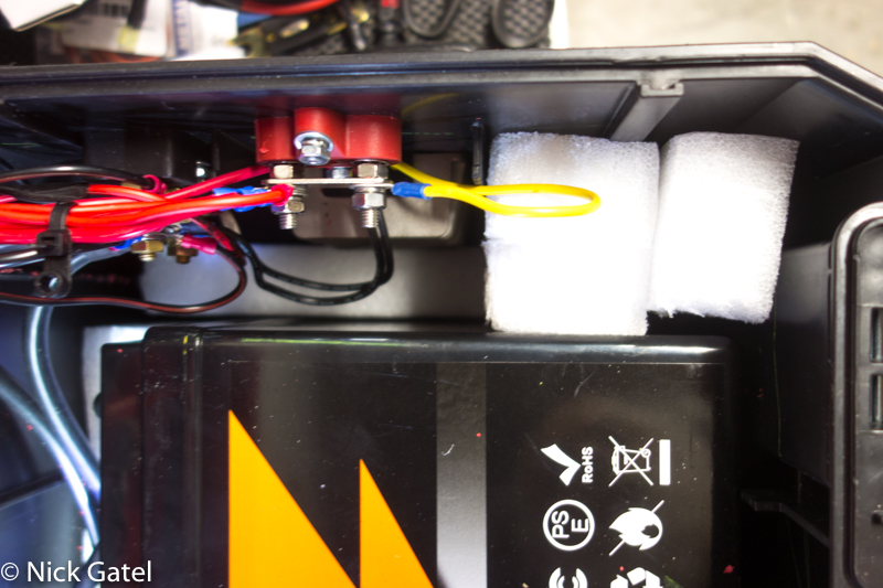
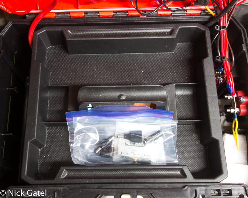
There is enough room inside the box to keep the tool tray that came with the Craftsman VersaStack toolbox. This will be handy for storing wire looms and other miscellaneous piece that I use frequently.
Solar Panel for the Remote Power System
I use my telescopes year round. The days are shorter in winter and the sun is lower in the sky, thus providing fewer hours of solar power to harvest each day. So we need to size our solar array for the months of the least amount of sunlight.
Peak Sun Hours
Peak sun hours is way to determine how much energy can be harvested during different times of the year. Below is a monthly chart of the Sun’s angle for my location:
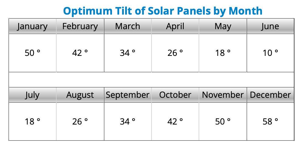
For our location, recommended panel angles:
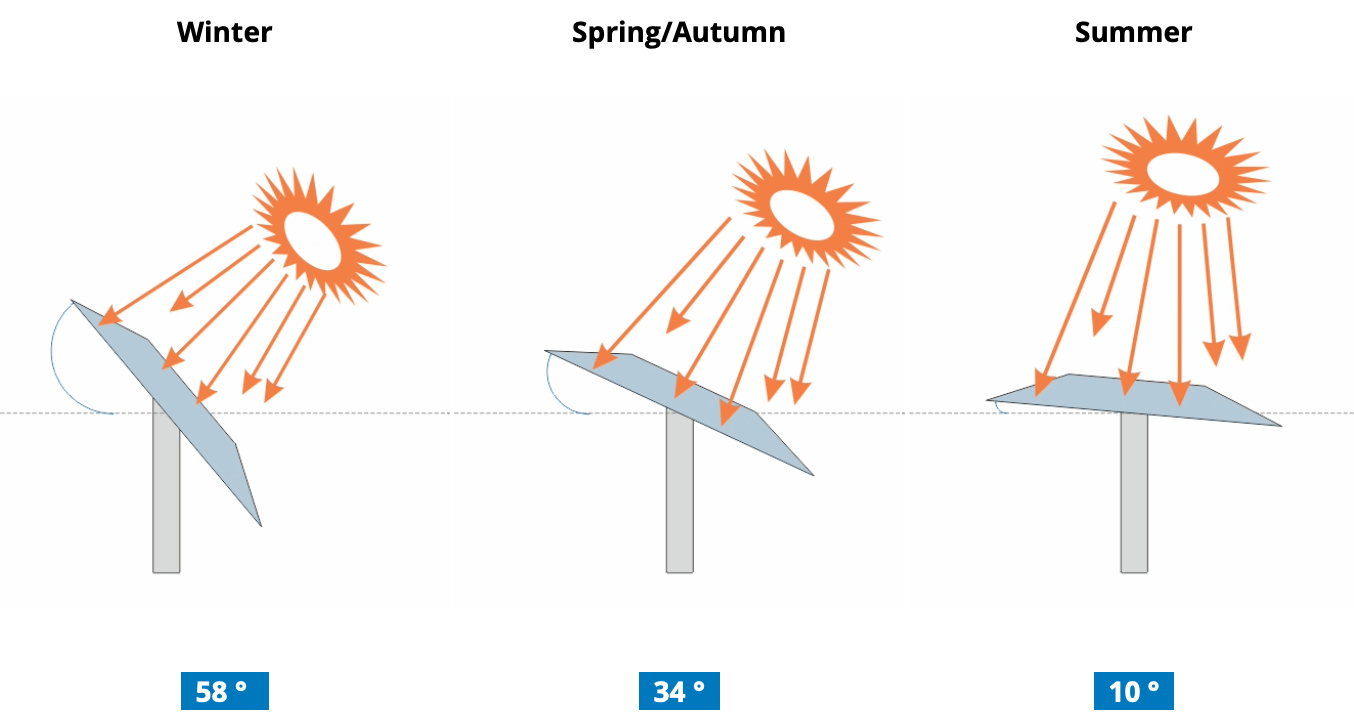
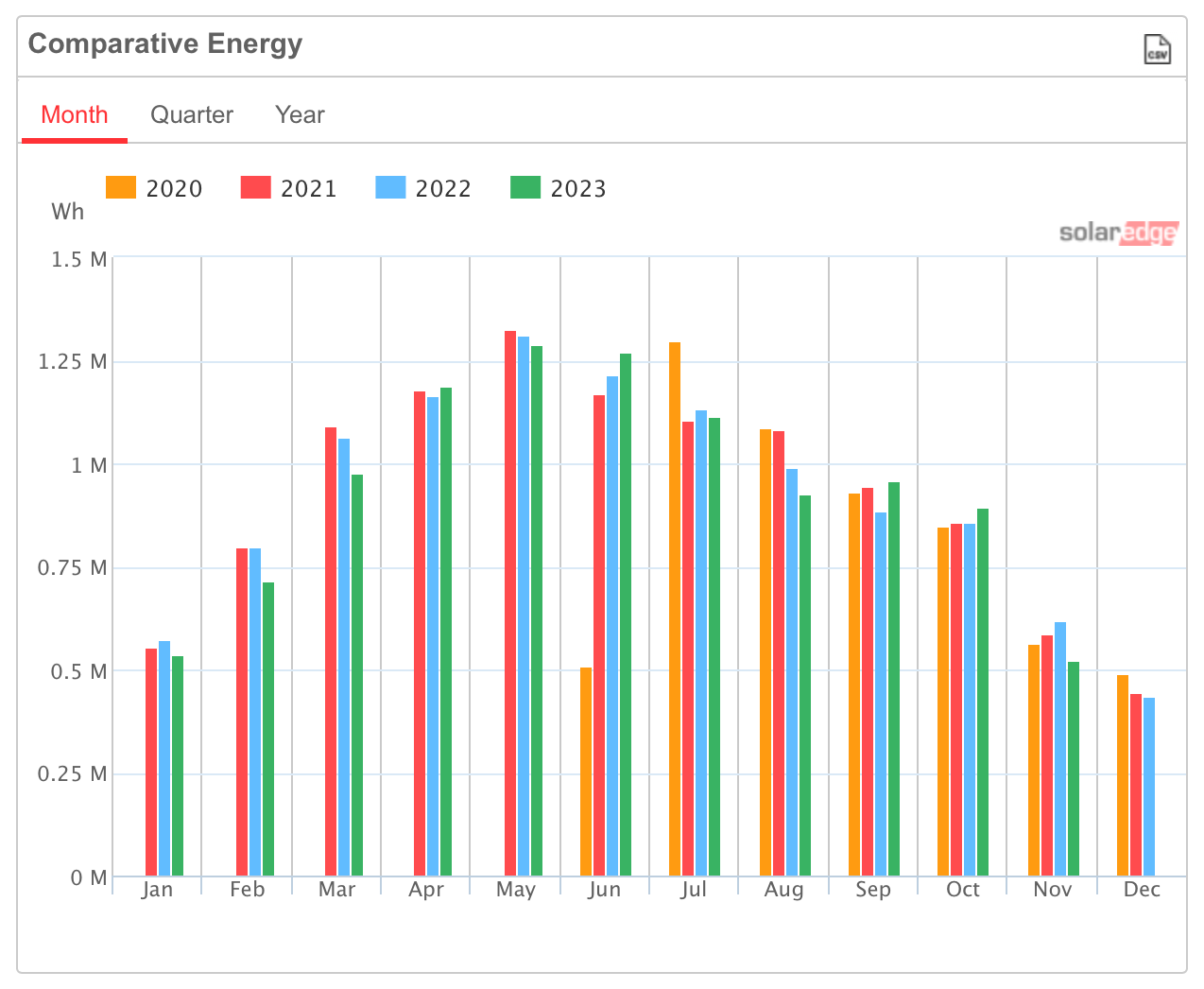
Fixed angle (non-tillable) solar panels do create compromise. Our house has a 6.2 kWh solar array with a fixed angle. Below is the monthly solar production. This is actual production, which is also impacted by weather and clouds, along with the Sun’s location in they sky. We typically have some monsoon cloud cover in the July through September. July of 2020 was unusually sunny every single day.
Peak Annual Sun Hours By Month For Palm Springs
Our travel trailer has permanently mounted panels on the roof and they are horizontal (0° angle). Below is the monthly hours of Peak Sun with horizontal panels. For our travel trailer, I would want to use the December number to calculate how much solar I need.
FLAT PANELS (HORIZONTAL)

TILT PANELS (ADJUSTED EACH MONTH TO OPTIMAL ANGLE)

This is the link to the Peak Sun Hours Calculator I used for the examples above. I like it because it shows each month of the year.
Renogy 100W Suitcase Solar Panel Kit
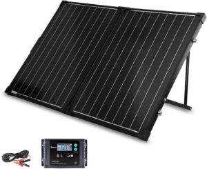
I bought a Renogy 100W suitcase solar panel kit with a PWM solar charge controller. It consists of two 50 watt panels hinged together with a carry handle. Construction of the panels (monocrystalline) seems robust and it comes included with a padded carrying case for transport. I only plan on using it on our frequent camping trips. It should be durable.
Since I will be using this suitcase solar panel for my astronomy kit, I can adjust the tilt angle. Calculating for the least amount of Peak Sun Hours (December), a 58° tilt angle, and assumed the panels would be facing directly south the entire day. I could harvest a little more energy if I move the panels to follow the Sun’s movement across the sky. This calculation will give me the amount of power I can harvest in the “worst” month of the year. I will be able to better in all of the other eleven months of the year.
Calculations
My last post Solar Charge Controllers: PWM vs. MPPT goes into great detail on calculations.
To calculate how large a panel I need for my system, I am going to use the 5.66 hours of peak sunlight from the table above, which is the shortest month of the year for Peak Sun Hours where I live. I also will use the specifications for the Renogy 100W suitcase solar panel with a 20A PWM solar controller.
The Optimum Operating Current (Imp) is 4.94 amps. We will multiply this by 5.66 peak hours.
4.94 amps X 5.66 hours = 26.96 Amp-Hours
Plenty to recharge the 100AH battery after a single night using just one of my astronomy telescope kits. Not even close to recharging if kits are used during the night, which both together consume around 44AH.
So I really need a 200W system. I could add another Renogy 100W suitcase solar panel to double the amount harvesting, bringing my total harvest to 55.92AH.
I haven’t spent time to monitor the actual performance of the Renogy 100W panel over time. But with the panel tilted at 58° it does produce 5.7 amps of power at times (which I confirmed with my TriMetric Battery Monitor).
This isn’t surprising as I have seen often seen this (solar output above the panel specifications) with my other solar systems over the years, where the solar will occasionally hit a peak like this for a while.
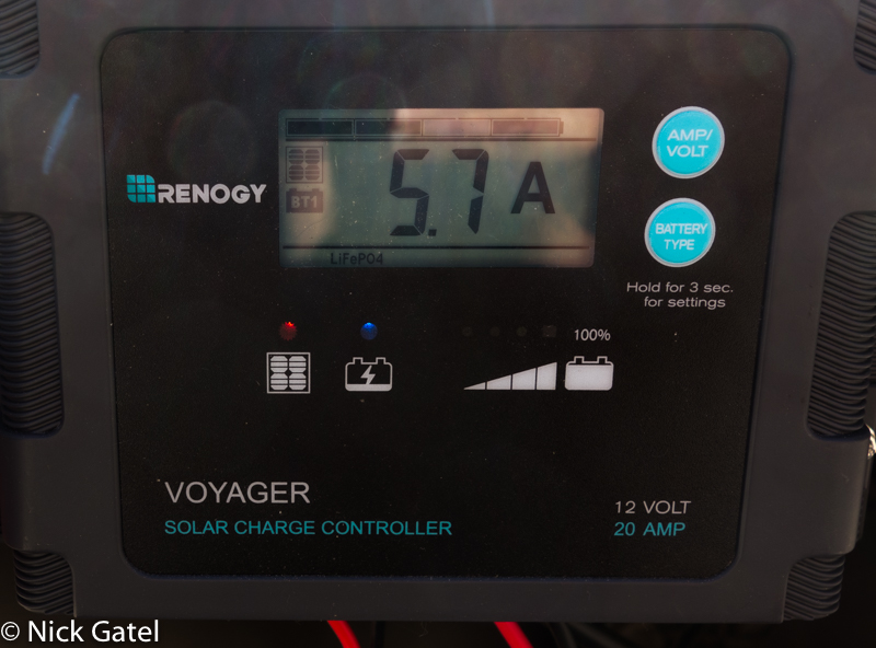
For sizing your own solar system, use the Optimum Operating Current (Imp) specification for your calculations.
SHOULD I BUY A SECOND SOLAR PANEL?
For me the answer is no.
I normally charge this battery with 120V AC power supply in my garage. Our house has solar and each year the utility company owes me money, so it is “free” electricity.
This solar panel is for camping trips where I normally just use one of my telescope rigs. Should I take both rigs camping, I can use the travel trailer’s solar system to recharge this battery.
WHAT I DON’T LIKE ABOUT THE SOLAR PANEL KIT
The solar controller is attached to the back of the panels with a folding hinge. Very convenient for packing up and transport. But a solar controller should be as close as possible to the battery, not the panels. For this small system it shouldn’t matter much.
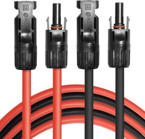
The kit comes with a battery charge cable with two clamps. Clamps aren’t secure and are really temporary. I bought a pair of 5FT 12 gauge solar extension cables then replaced the standard solar cable connectors at one end with Anderson Power Pole connectors for a secure connection to the battery. Anderson Power Poles are standard for almost all my 12V DC electric projects.
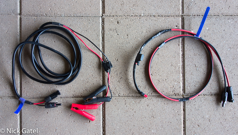
The Renogy suitcase solar kit came with a charge cable (above left) with rather thin wires and clamps. I made a more secure and shorter cable (above right) with Anderson Power Pole connectors and an inline 15A ATC type fuse.
What follows is a list of most of what I used with links, should you want to do something similar:
-
- LiTime 100Ah LiFePo4 Battery – no low temperature cutoff (Amazon)
- Renogy 100 Watt Suitcase Solar Panel with 20A Charger Controller (Amazon)
- PowerWerx Regulated Power Supply (Amazon)
- Craftsman VersaStack Toolbox (Amazon and also available from Lowe’s)
- Single Anderson Power Pole Panel Mount (Amazon)
- Double Anderson Power Pole Panel Mounts (Amazon)
- 6 gauge battery cables 3FT (Amazon)
- 6 gauge battery cable 1FT – just need one black negative (Amazon)
- Battery terminal posts (Amazon)
- ON/OFF switch (Amazon)
- TriMetric Battery Monitor (Direct from manufacturer (Bogart Engineering)
- Panel Mount Voltmeter panel mount (Amazon)
- 22 Gauge 4 Conductor Wire Signal wires for TriMetric Battery Monitor (Amazon)
- 16AWG ATC inline fuse holder (Amazon)
- 10A ATC Fuse (Amazon)
- WAGO Lever Nuts (Amazon)
- Power Pole panel mount – double – 2 ea (Amazon)
- Power Pole panel mount – single (Amazon)
- Double USB Power Port (Amazon)
- 12V Cigarette Lighter Power Port (Amazon)
- Buck-booster (Amazon)
- 100A 100mV Shunt (Amazon)
- Positive Bus Bar (Amazon)
- Power Pole connectors (Amazon)
- Power Pole crimper (Amazon)
- A proper wire terminal crimper (Amazon)
- Wire terminal crimp ring connectors (Amazon)
- 16AWG Wire (Amazon)
